Why 77GHz radar PCB projects are harder than they look
A 77GHz radar PCB is not just another high-frequency board with a few extra layout rules. It sits at the point where antenna behavior, loss control, assembly discipline, and test strategy all start to matter at once. That is why engineers working on automotive sensing, industrial millimeter wave board designs, or other compact radar modules tend to spend far more time on verification than on the schematic itself.
For sourcing managers and product teams, the real question is usually not whether the board can be built. It is whether the board can be built consistently, then tested in a way that proves the design still behaves correctly after SMT, reflow, and integration into a larger system. A custom radar PCBA often looks straightforward on paper, but the manufacturing process can expose issues that never showed up in CAD.
What makes this class of board different
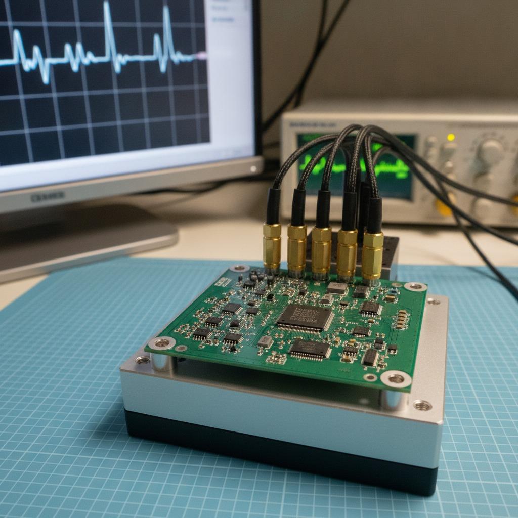
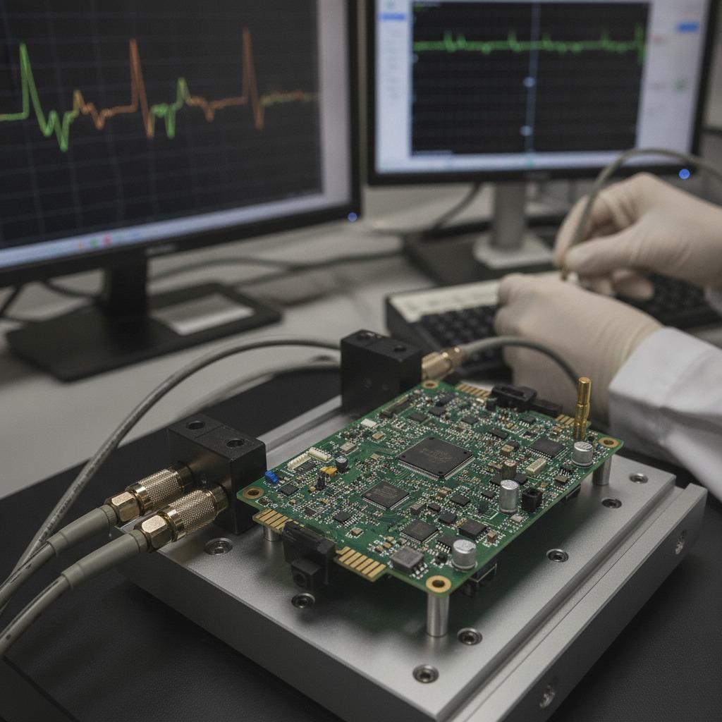
At 77GHz, small imperfections become visible in the RF response. Trace geometry, connector choice, board stack-up, component placement, and even how the board is held during probing can affect results. The visible lab setup in the provided product data is a good reminder of that reality: a board mounted in a fixture, connected to test equipment, with a waveform displayed on a monitor. That kind of bench workflow is common during bring-up because these assemblies rarely go straight from fabrication into final enclosure without an intermediate validation step.
In practical terms, buyers evaluating a vehicle electronic PCBA or similar high-frequency assembly should assume that testing is part of the product, not an afterthought. If the supplier only talks about fabrication and ignores validation, that is a warning sign.
Typical build elements on a radar PCB
While the exact board in the supplied data is not identified by model, the visible features are typical of a compact embedded or radar-related assembly: a green solder-mask PCB, fine-pitch integrated circuits, SMD passives, header pins, and corner mounting holes. That combination suggests a board intended for prototyping, control, or interface work rather than a sealed consumer device.
For a 77GHz radar PCB, the underlying structure may also include controlled-impedance routing, low-loss materials, and careful partitioning between RF and digital sections. The company profile for hcdpcba mentions multilayer boards, HDI boards, and high-frequency boards, which is relevant here because these jobs often require that sort of mixed capability: PCB prototyping, SMT assembly, component sourcing, and final test under one roof.
Selection criteria that actually matter
When comparing suppliers for an auto accessory PCB or a radar module for industrial use, the decision should rest on a few practical questions:
1. Can the factory handle high-frequency layout and assembly together?
Many shops can fabricate a board. Fewer can assemble it without damaging the signal path. At 77GHz, the handoff between design and production needs more than a generic DFM check.
2. Is test support built into the workflow?
hcdpcba states that it offers assembly and testing, along with DFMA support. That matters because radar and millimeter-wave boards usually need functional checks, not only continuity inspection. A board may pass basic electrical checks and still fail under actual waveform verification.
3. Is the supplier comfortable with custom work?
Custom radar PCBA projects often change during development. A good supplier should be able to support prototype spins, small-batch runs, and revisions without making the process feel like a one-size-fits-all catalog order.
Common mistakes buyers make
The most common mistake is underestimating test time. Teams budget for fabrication and assembly, then discover that the real schedule pressure comes from tuning, debugging, and rework. Another error is choosing a supplier based only on board count or advertised speed, without checking whether they understand RF-sensitive assembly.
A second mistake is treating the board as if it were a generic control module. A vehicle electronic PCBA designed for millimeter-wave sensing has tighter expectations than an ordinary embedded board. Even if the PCB shape is simple, the electrical behavior is not.
What a practical buyer should ask before ordering
Ask what level of testing is included. Ask whether the supplier can support prototype PCB assembly as well as later production. Ask how component sourcing is handled, especially for parts that may be long lead or sensitive to substitution. And ask what documentation you will receive back: test records, assembly notes, or design feedback.
That last point is easy to overlook. Yet for radar work, small comments from the factory can save an entire revision cycle. A board that looks fine in a screenshot may still need layout adjustments once the first physical unit is measured.
A note on the lab side of the story
The supplied image shows a test instrument, a display with a waveform trace, and a board on a fixture. That is exactly the kind of environment where embedded hardware bring-up becomes visible. It is not glamorous, but it is where many product risks are found early. For engineers, that is a good thing. For buyers, it is proof that the supplier should think beyond fabrication and into validation.
FAQ
Is a 77GHz radar PCB the same as a normal high-speed PCB?
No. It may share some fabrication steps, but the RF constraints are far tighter and the validation process is usually more demanding.
Can an industrial millimeter wave board be built in small quantities?
Yes, and often it should be. Early-stage radar projects usually benefit from prototype and pilot runs before production scaling.
What should I prioritize first: cost, speed, or test capability?
If the design is truly high-frequency, test capability should come first. A low-cost board that cannot be verified is expensive in the end.
Next step
If you are sourcing a 77GHz radar PCB, start by defining what the supplier must do beyond assembly: prototype support, SMT, component sourcing, and functional test. hcdpcba positions itself around those capabilities, including PCB prototyping, SMT贴片, assembly, testing, and DFMA support for industrial, automotive, medical, and communications applications. For teams trying to shorten the loop between design and measured results, that combination is usually the right place to begin the conversation.