Modern AI vision systems rely on continuous image acquisition and high-speed data processing. Cameras capture large volumes of visual information that must be transmitted, processed, and analyzed without interruption. In real deployments—such as industrial inspection, intelligent surveillance, and autonomous devices—any instability in hardware can lead to data loss or incorrect analysis.
Many AI hardware teams encounter problems only after systems begin operating under real workloads. Image latency increases, sensor communication becomes inconsistent, or processing units throttle due to localized heat buildup. These issues are rarely caused by the camera sensor itself. In many cases, they originate from board-level design limitations.
A well-engineered AI vision PCBA addresses these challenges by coordinating signal routing, sensor interface design, and thermal distribution within the board architecture. By aligning these factors early in development, our engineering team ensures that image data flows smoothly from sensor to processor even under continuous processing workloads.
Why Vision Processing Hardware Demands Specialized PCBA Design
Unlike conventional embedded boards, vision hardware must handle constant streams of image data. A single high-resolution sensor can generate hundreds of megabytes of data every second. When multiple sensors or neural processors are integrated into the same board, the hardware must maintain extremely stable communication paths.
Small layout imperfections that would be insignificant in other systems can become critical in vision applications. For example, minor impedance inconsistencies along sensor data lines may introduce noise or timing mismatches that disrupt frame synchronization.
A reliable AI vision PCBA therefore focuses on maintaining consistent signal timing between sensor modules, processing units, and memory interfaces. When routing symmetry and impedance control are properly implemented, systems often show measurable improvements in frame stability and reduced data transmission errors.
Engineering teams implementing these practices typically see 15–20% improvement in high-speed signal stability compared with conventional routing methods.
Material and Structural Design for Vision Processing Boards
The material system of the PCB strongly influences both signal behavior and thermal performance. Vision systems frequently operate in compact enclosures where heat generated by processors, sensors, and memory accumulates rapidly.
Standard FR-4 laminates remain widely used, but higher-performance materials are often selected when signal frequencies or thermal loads increase. Low-loss dielectric materials help preserve signal quality across long sensor-to-processor connections, while thicker copper layers improve current handling and thermal spreading.
Stack-up architecture is equally important. Multi-layer structures allow designers to isolate sensitive image sensor signals from switching power circuits. In typical vision processing boards, dedicated ground planes stabilize signal reference paths and reduce electromagnetic interference.
When these structural considerations are incorporated into AI vision PCBA, the system gains both electrical stability and improved thermal balance, which are essential for continuous image processing.
Managing Sensor Data Through High-Speed Interfaces
Image sensors communicate with processing units through high-speed interfaces such as MIPI CSI or similar high-bandwidth protocols. These interfaces require extremely consistent trace geometry and differential routing.
If trace lengths differ significantly or reference planes are interrupted, signal skew can occur. This may cause dropped frames or synchronization errors that appear intermittently during operation.
In a robust AI vision PCBA, signal routing is carefully matched to maintain consistent propagation timing. Differential pairs are length-matched, impedance-controlled layers are used for sensor data channels, and return paths are preserved to minimize noise coupling.
These design practices help maintain stable frame transmission and reduce the probability of intermittent data errors in complex vision systems.
Thermal Management in Continuous Vision Processing
AI vision hardware often operates continuously, especially in industrial inspection or security applications. This sustained workload means processors and accelerators generate heat for extended periods.
Without careful thermal planning, heat accumulates around compute clusters and sensor interfaces, eventually degrading performance. Even a temperature increase of 15–20°C can reduce semiconductor lifespan significantly.
Thermal optimization within AI vision PCBA includes balanced copper distribution, thermal via arrays beneath high-power components, and strategic component placement to avoid heat concentration.
In practical deployments, these measures frequently reduce localized hotspot temperatures by 10–25°C, allowing systems to maintain stable performance under prolonged operation.
Manufacturing Consistency and Image Processing Stability
Vision hardware is sensitive to small electrical variations introduced during manufacturing. Minor differences in solder volume or component alignment can influence signal impedance or thermal contact.
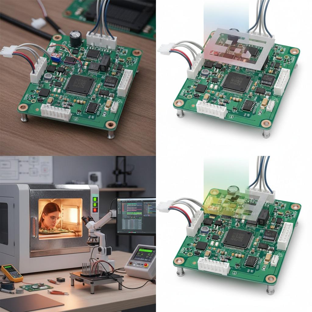
Maintaining consistent assembly conditions is therefore essential. Stable stencil design, accurate component placement, and controlled reflow profiles ensure that each production batch behaves electrically the same way.
Manufacturing Factors Influencing Vision PCBA Performance
| Manufacturing Factor | Control Method | Typical Impact |
|---|---|---|
| Differential routing | Length-matched layout | Reduced signal skew |
| Layer structure | Controlled impedance stack-up | 15–20% signal stability improvement |
| Copper distribution | Balanced thermal paths | Lower hotspot formation |
| Component placement | Precision placement accuracy | Stable sensor interface performance |
| Process consistency | Controlled reflow conditions | Reduced batch variation |
Through these controls, a production-ready AI vision PCBA maintains stable image processing performance even as manufacturing volumes increase.
Compliance and Reliability Considerations
Vision systems deployed in commercial environments must also meet regulatory standards for electromagnetic compatibility and electrical safety. High-speed data signals and switching power circuits can generate significant electromagnetic emissions if not carefully managed.
By integrating grounding strategies, layer isolation, and shielding structures into the board architecture, designers can reduce the risk of failing certification tests. Designing compliance requirements into the PCBA stage significantly shortens the path to product deployment.
Frequently Asked Questions
Q1: Why do AI vision systems sometimes lose frames or experience latency?
Signal integrity problems or thermal throttling at the PCBA level can disrupt high-speed sensor communication.
Q2: Does PCB material affect camera data quality?
Yes. Signal loss and impedance variation in PCB materials influence high-speed sensor communication.
Q3: Can manufacturing variation affect image processing stability?
Yes. Even small assembly variations can influence signal timing and thermal behavior.
Why Vision System Reliability Begins at the PCBA Level
A well-designed AI vision PCBA ensures that image sensors, processors, and memory communicate reliably under real operating conditions. When signal integrity, thermal distribution, and manufacturing discipline are aligned, AI vision systems deliver consistent performance even in demanding environments.
If you want to evaluate how board-level architecture influences the reliability and scalability of vision hardware, reviewing real PCBA capabilities is a practical starting point. You can learn more about our engineering and manufacturing experience here:
👉 https://www.hcdpcba.com
For projects involving AI cameras, machine vision systems, or real-time image processing hardware, discussing your requirements early can significantly reduce development risk. Our engineering team is available for consultation here:
👉 https://www.hcdpcba.com/en/contact-us