
Power Bank PCBA Overview
A power bank pcba is the control center inside a portable charger, and it solves a common buyer problem: turning a battery pack into a usable USB power source with charging, discharge management, and status indication in one compact assembly. For OEM brands, repair teams, and DIY product builders, this kind of module reduces wiring complexity and helps standardize the electronics inside a handheld power bank enclosure.
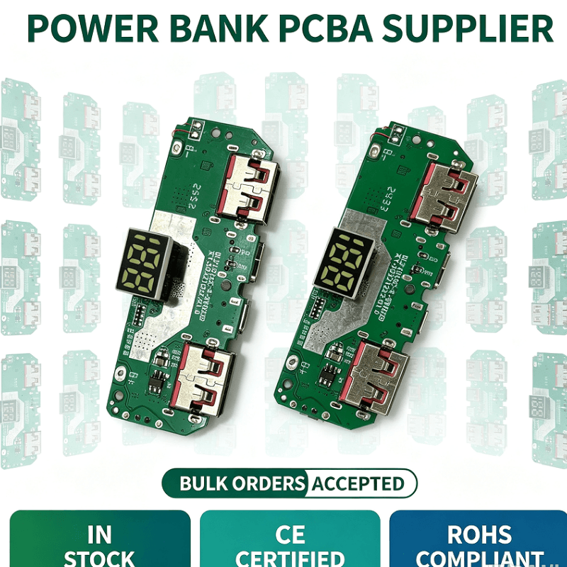
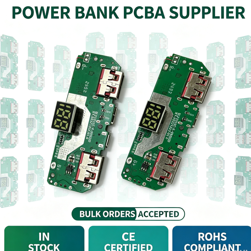
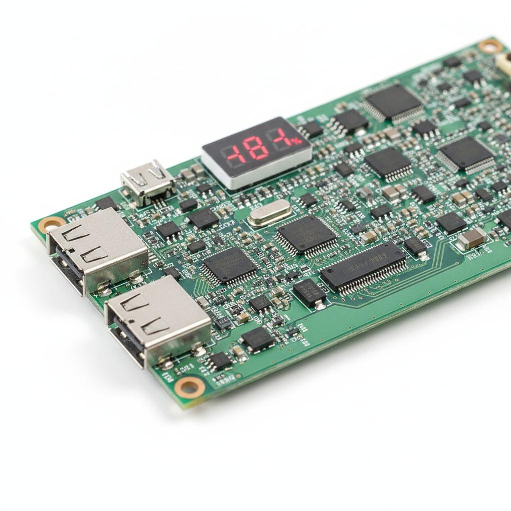
The product shown is an assembled power bank control board with visible USB output ports, a micro-USB-style input port, small surface-mount components, and a digital display. It appears to be a finished PCBA rather than a bare board, which means it is intended for integration into a portable charger build or for replacement use in existing battery-pack housings.
What the Board Does
In a portable charger, the circuit board manages the interface between the battery cell and the external device. That usually includes battery charging, output conversion, and display feedback. The visible layout suggests a practical mobile power pcba designed for compact consumer electronics. The integrated display helps users check operating status at a glance, while the USB ports make the module suitable for direct device charging.
Because only the image is available, exact electrical ratings cannot be confirmed. Buyers should treat the board as a power bank circuit board for integration and verify voltage, current, battery compatibility, and charging protocol before production use.
Visible Structure and Key Features
Board construction
The assembly uses a green FR-4 PCB with solder mask and white silkscreen markings. That is a standard structure for consumer electronics and gives the module a familiar, manufacturable base for repeated assembly.
Connectors and display
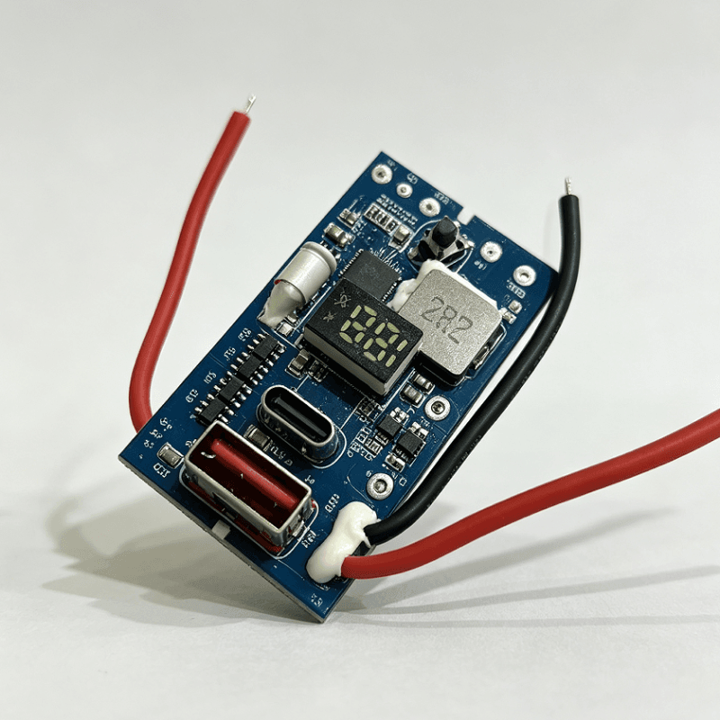
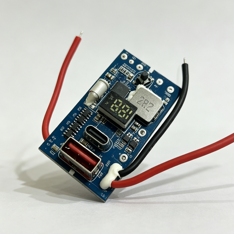
Several ports are visible on the board, including two USB-A female connectors, a smaller micro-USB-style port, and another rectangular connector on the side. A 2-digit 7-segment LED display is mounted on the board for numeric readout, likely showing battery level or output status. These visible features make the board suitable for user-facing portable charging products.
Assembly style
The board includes mixed SMT and through-hole components, along with small wire leads on at least one version shown in the supplied data. This type of assembly is typical of a power bank motherboard built for compact packaging and repeated production.
Materials and Finish Options
From the image, the main visible material is standard fiberglass PCB substrate with a green solder-mask finish. The connector housings appear metal-shielded, and the display uses a dark translucent plastic window. These are common choices for consumer-grade charging modules because they balance assembly efficiency, durability, and cost control.
For production projects, the finish can often be adjusted depending on the OEM/ODM requirement. Common options in this product category may include changes to silkscreen, connector layout, indicator style, solder mask color, and board shape, subject to design rules and manufacturability.
Manufacturing Process
This type of power bank pcba usually involves PCB fabrication followed by SMT assembly and connector soldering. The process may also include functional testing, visual inspection, and packaging for integration into a battery enclosure. In a controlled manufacturing workflow, DFM and DFMA review can help reduce assembly issues around port placement, component spacing, and mechanical fit.
Because the board is intended for electrical power handling, connector solder joints, trace routing, and component placement are especially important. A compact power bank control module has to fit into a narrow enclosure while still leaving room for battery cells, insulation, and heat dissipation paths.
Typical Applications
This power bank motherboard is relevant for several buyer groups. It can be used in OEM portable charger products, replacement battery-pack modules, small-batch consumer electronics builds, and DIY power bank projects. It is also a practical option for repair shops that need a replacement control board for a damaged portable battery enclosure.
For sourcing teams, the board may fit into product lines such as travel chargers, emergency backup power products, branded mobile charging units, and custom promotional power banks. The visible display and multiple ports make it easier to build a user-friendly product without adding separate indicator hardware.
Quality Control and Buyer Checks
Good PCBA quality depends on more than the visible layout. Buyers should confirm solder joint consistency, port alignment, display readability, and board-to-enclosure fit. If the board will be used in volume production, electrical test and functional test should be part of incoming inspection or factory verification.
The image data mentions CE and RoHS marks, but those claims are not independently verified here. Buyers should request supporting documents if certification status matters for their market. It is also wise to confirm battery chemistry compatibility, protection requirements, and the exact function of each port before integrating the module into a finished product.
Customization Guidance for OEM and ODM Projects
When sourcing a mobile power pcba, customization usually starts with the mechanical and electrical interface. Buyers may need a different connector arrangement, display position, board outline, or wire lead length depending on the enclosure design. If the product is being developed for retail sale, the indicator behavior and port labeling should also match the user experience plan.
hcdpcba supports SMT assembly, PCBA production, PCB prototyping, component sourcing, assembly, testing, and OEM/ODM service. For a project like this, that means the buyer can discuss board fabrication, assembly flow, and test requirements together instead of treating them as separate vendors. That approach is useful when the goal is to build a repeatable power bank control module for mass production.
How to Evaluate This Product for Your Project
Before placing an order, compare the board against your product requirements in five areas: enclosure size, battery type, output port layout, display needs, and test standard. If your project needs a ready-to-integrate power bank circuit board, ask for the electrical specification, connector pinout, and mechanical drawing. If you are repairing an existing unit, check whether the port arrangement and mounting points match the original device.
For buyers focused on production efficiency, the most important questions are usually compatibility, stability, and assembly repeatability. A well-made board can reduce manual wiring, simplify final assembly, and improve consistency across batches.
Request a Quote or Technical Review
If you need a power bank pcba for OEM production, replacement, or custom integration, send your target specification, enclosure drawing, and expected function list for review. hcdpcba can support PCB fabrication, SMT assembly, component sourcing, testing, and tailored production workflows for portable charging electronics.
For project discussion or quotation, contact the team at +86 18924624188 and share your board requirements, quantity target, and customization needs.