
DIY Power Bank PCBA Module Overview
The DIY Power Bank PCBA Module is a compact power electronics board designed for builders who need a practical way to manage USB-based power in a small enclosure or custom device. It helps solve a common project problem: converting battery or DC input into a usable USB power interface without designing a full circuit from scratch. Based on the visible hardware, this module appears to combine power regulation, USB connection points, and an on-board display for status or measurement, although the exact circuit topology is not confirmed from the image alone.
For prototyping teams, repair shops, and OEM buyers, the appeal is straightforward. A ready-made power board reduces assembly time, shortens debugging cycles, and provides a repeatable foundation for portable chargers, test fixtures, and embedded USB power systems.
What Is Visible on the Board
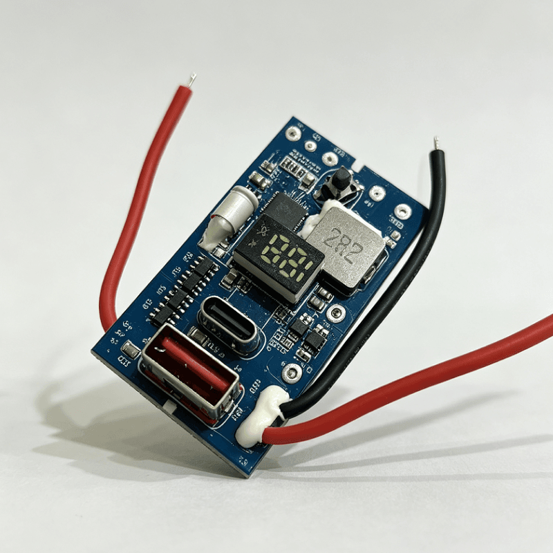
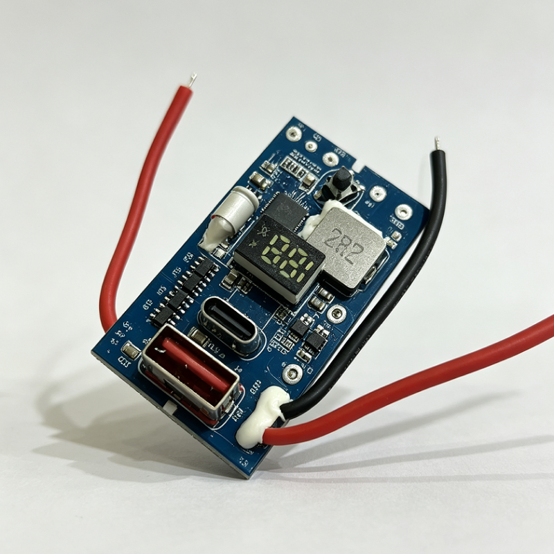
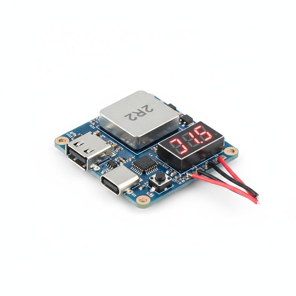
This board is built on a blue FR-4 printed circuit board with mixed surface-mount parts and connector hardware. Several details are visible at a glance: a large shielded inductor marked “2R2,” a controller IC, a 7-segment digital display, a tactile button, and multiple wire leads in red and black. The board also shows both USB-A and USB-C style interfaces, which suggests it may support power access through different connector formats.
The presence of the inductor indicates a switching power stage, but it is not safe to claim whether the module is a buck converter, boost converter, buck-boost circuit, or charger board. Buyers should treat the image as evidence of a power management function, not a full electrical specification.
Key Specifications and Capabilities
Visible construction features
The module appears to include a compact layout suited to dense electronics packaging. The connector set includes a USB-A female port and at least one USB-C connector, while the attached leads allow direct soldered integration into a larger assembly. The digital display may be used for voltage, current, or mode information, but that function is not confirmed.
Practical capabilities for builders
In a custom design, a board like this is often used to distribute power, supply USB devices, or support battery-powered electronics. It may also serve as a control element in a Power Bank Assembly where the buyer wants a prebuilt board rather than a fully discrete design. Because the electrical ratings are unknown, the safest buying approach is to verify input range, output limits, and protection behavior before committing to production.
Materials and Finish Options
The visible material set is standard for modern electronics manufacturing: FR-4 laminate, blue solder mask, white silkscreen, tinned solder joints, metal connector shells, and insulated wire leads. These are common choices for cost-effective consumer and industrial modules. The solder joints at the wire connections appear to include adhesive or potting material for strain relief, which is helpful in handheld or vibrating environments.
If you are planning a similar power bank circuit board, finish options usually depend on the final use case. A compact prototype may only need basic solder mask and standard HASL or ENIG surface finish, while a higher-reliability product may benefit from tighter process control, stronger mechanical support, and more thorough post-assembly cleaning.
Manufacturing Process and Assembly Flow
From a production standpoint, this kind of board typically combines PCB fabrication, SMT assembly, connector soldering, and final electrical inspection. The surface-mounted ICs and passives are placed by pick-and-place equipment, then reflow soldered. Larger parts such as USB connectors, displays, buttons, and wire harnesses are often added in a second assembly step. If the design includes a Lithium Battery Protection Board function, that part of the system should be checked separately, since protection circuitry and charging circuitry are not always combined on the same PCB.
hcdpcba supports PCB prototyping, SMT贴片, component sourcing, assembly, and testing. For a module like this, that means the production path can move from sample build to small batch manufacturing without changing suppliers. The company also offers DFMA support, which is useful when a buyer wants to simplify the layout, reduce rework, and improve manufacturability before volume production.
Typical Application Scenarios
This kind of module fits several project categories. It can be used in portable power supply builds, USB device power conversion, embedded electronics prototyping, bench testing setups, or repair workflows where a stable USB interface is needed. For a compact consumer device, the board may also support charging or regulated distribution where both USB-A and USB-C ports are desired.
In a lab or workshop, the built-in display and pushbutton make the board easier to observe and adjust than a fully hidden power stage. That can save time during troubleshooting and initial validation.
Quality Control Considerations
For buyers, the real value is not just the visible hardware. It is the consistency of assembly, solder quality, connector alignment, and functional test coverage. A power module should be checked for polarity errors, short circuits, connector integrity, and stable operation under load. If the board is intended for repeated plugging and unplugging, the USB interfaces and wire terminations deserve special attention.
Good manufacturing practice also includes incoming component verification, reflow profile control, and final electrical testing. For custom OEM or ODM work, buyers should request a clear test plan so the assembly team knows which performance points must be verified before shipment.
Customization Guidance for Buyers
If you need a similar board for your own product, start by defining the actual power path: battery to USB, DC input to regulated output, or charging plus protection in one chain. Then clarify connector type, display behavior, board size, wire length, mounting holes, and any enclosure constraints. A clear brief helps avoid redesign later.
For teams building a Power Bank Assembly or a small adapter product, the most important buyer decision factors are electrical ratings, protection architecture, connector durability, and testability. If the product will be sold commercially, also confirm compliance requirements, because those details are not visible on the board image alone.
Request a Custom Build
hcdpcba can support PCB打样, SMT assembly, component sourcing, assembly, and testing for custom power modules and related electronics. If you need a prototype of a DIY Power Bank PCBA Module or want to refine an existing power bank circuit board for production, share your schematic, target dimensions, connector layout, and test requirements. A well-prepared specification will make it easier to move from concept to working hardware with fewer revisions.