BLDC Ceiling Fan Controller PCB Overview
The BLDC Ceiling Fan Controller PCB is designed to solve a common problem in ceiling fan systems: how to coordinate motor speed, lighting, sensor feedback, and smart connectivity on one compact control board. In a fan hub where space is tight and wiring is exposed to vibration, heat, and repeated start-stop cycles, the control PCB becomes the real center of operation. For manufacturers and repair teams, this kind of board helps simplify integration while keeping the electrical layout organized and serviceable.
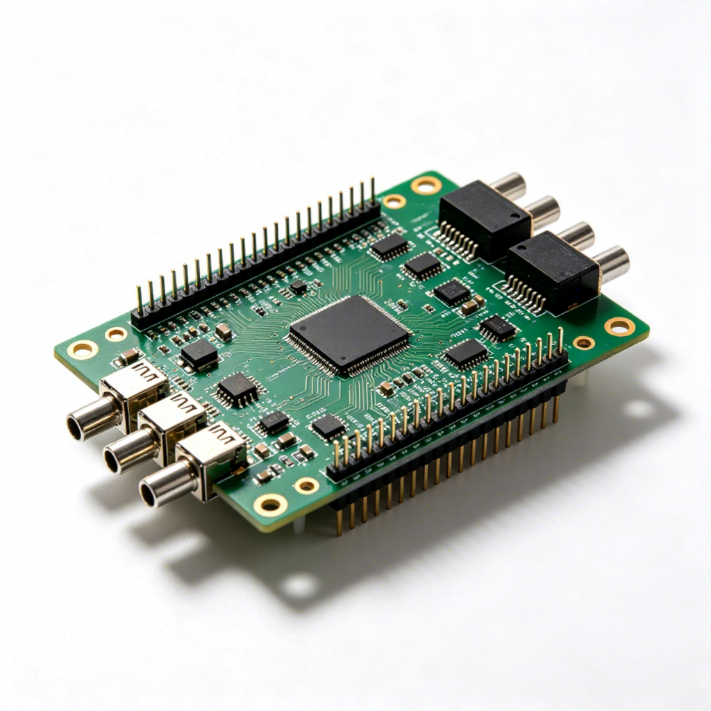
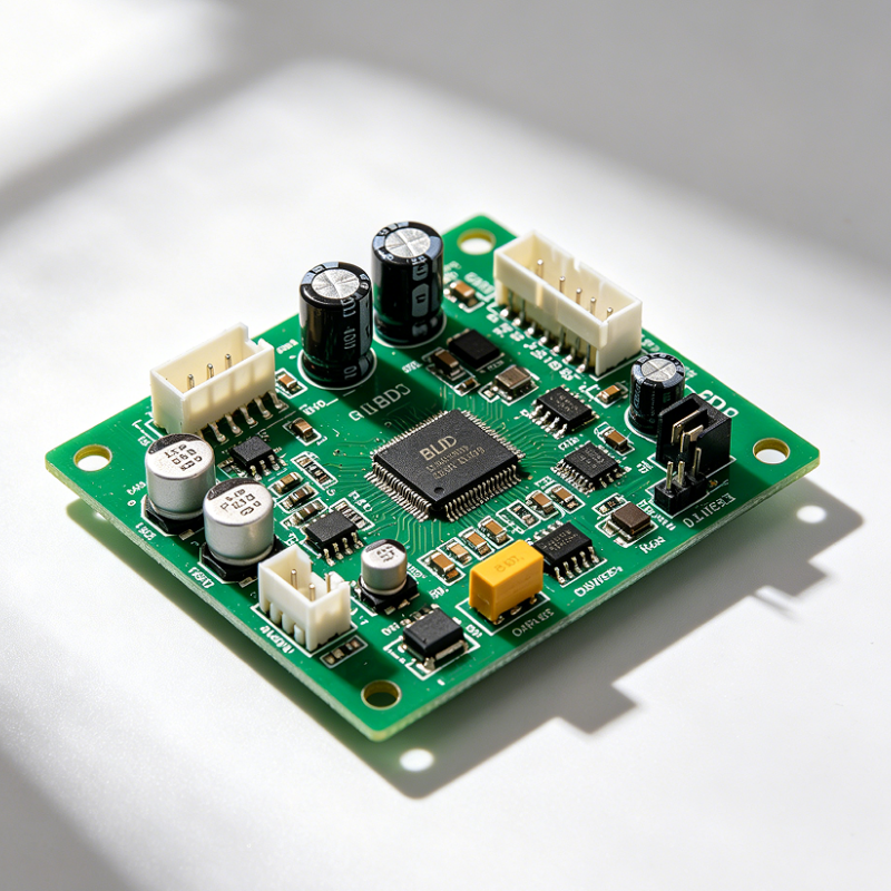
Based on the visible assembly, this is a populated PCB/PCBA rather than a bare board. It shows a central controller IC, multiple support chips, electrolytic capacitors, power and signal connectors, and corner mounting holes for fixed installation. The board appears suitable for embedded appliance control, and the layout suggests it may manage functions such as motor control output, lighting interface connections, speed sensor input, and wireless module expansion. Exact electrical ratings and firmware behavior are not identifiable from the image alone, so any final specification should be confirmed during sample review or engineering communication.
Product Structure and Functional Layout
The board uses a compact rectangular layout with a mix of surface-mount and through-hole components. That structure is common in appliance electronics because it balances signal density with practical wiring access. Several labeled connector areas are visible, including power input and output sections, which makes the board easier to integrate into a complete fan system. A dedicated Wi‑Fi module connection port is also visible on the board image, indicating that the design may support remote control or smart-home expansion.
For buyers evaluating a BLDC Ceiling Fan Controller PCB, these visible connection points matter as much as the chip count. A ceiling fan platform often needs separate paths for supply input, motor drive, sensor feedback, and lighting control. When each interface is clearly separated, assembly becomes cleaner and troubleshooting is faster during production or maintenance.
Visible interface features
From the provided data and image, the board appears to include:
- Power input connection
- Motor control output section
- Speed sensor input
- Lighting interface and lighting control interface
- Wi‑Fi module connection port
- Multiple plug-in headers for wiring harness integration
- Corner mounting holes for mechanical fastening
Materials, Surface Finish, and Assembly Style
The substrate appears to be FR-4-style PCB material with a solder mask finish and exposed copper pads under mounted components. The visible green solder mask is typical for industrial electronics, while the white board marking and connector placement support organized assembly. Large electrolytic capacitors indicate that the design likely includes power smoothing or energy buffering, which is common in motor-control circuits.
The board is assembled with SMT components and likely reflow soldering, which is standard for high-density control electronics. The presence of several connectors and larger components also suggests a mixed-technology build. For OEM and ODM buyers, that combination is useful because it supports automated placement while still allowing practical cabling and field service.
Manufacturing and PCBA Services
hcdpcba provides PCB fabrication, SMT assembly, component sourcing, assembly, and testing services for custom electronic products. For a BLDC Fan Driver PCBA project, this means the board can be handled as a complete build rather than a set of separate parts. Design-for-manufacturing support is especially important in appliance control electronics, where connector positions, component spacing, thermal loading, and assembly access can affect reliability.
Through OEM and ODM support, buyers can move from schematic or sample reference to a finished board with consistent production control. If the target product needs a 110-240V BLDC Ceiling Fan Control Board or a similar household appliance controller, the engineering team can review the layout, component availability, and assembly sequence before mass production. Final capability should always be confirmed against the approved design files and sample test plan.
Typical Applications
This kind of control PCB is relevant for ceiling fans, smart fan retrofit kits, appliance control modules, and embedded motor-and-lighting systems. The visible fan-hub context suggests ceiling fan use, but the board architecture could also fit other compact control environments where a motor, sensor, and lighting load need to be coordinated. For buyers in smart home manufacturing, the Wi‑Fi expansion point may be useful for remote operation or connected features.
Possible application scenarios include residential ceiling fans, replacement control modules, fan speed regulation systems, lighting integration boards, and low-profile embedded control units for household equipment. The board’s compact footprint and connector-based design make it suitable for products that must be assembled quickly and maintained without a complex internal harness.
Quality Control and Buyer Considerations
When choosing a BLDC Ceiling Fan Controller PCB, buyers should focus on the practical details that affect production and service life. Key points include connector type, mounting hole position, component sourcing consistency, thermal design, firmware support, and whether the board layout fits the target enclosure. If the board will be used in a production ceiling fan, compatibility with the motor set, sensor arrangement, and lighting hardware must be checked early.
Quality control for this type of product usually includes visual inspection, solder joint verification, polarity checking, and functional testing of key interfaces. For a custom project, it is also wise to define the test points and acceptance criteria before pilot production. That reduces surprises when the board moves from sample stage to volume assembly.
Customization Guidance
Customization is often the main reason buyers request a dedicated controller PCB. Connector placement can be changed to match a fan housing, the control logic can be aligned with a specific motor platform, and the board can be adjusted for different interface requirements. If the product needs a FOC Silent Speed Control Ceiling Fan PCB concept, the engineering brief should clearly describe the motor type, expected control method, input range, interface count, and any smart-control requirements.
To speed up development, buyers should prepare schematic files, mechanical drawings, preferred connector specifications, and any mandatory functional sequence. If only a reference sample is available, a detailed sample review can help define what is visible, what is uncertain, and what needs to be validated by testing.
Request a Quote
hcdpcba supports PCB prototyping, SMT assembly, component sourcing, and full PCBA delivery for custom control boards. If you need a ceiling fan controller board, a motor control module, or a related smart appliance PCB, share your drawings or reference sample for a manufacturing review. The result is a board built around your enclosure, wiring, and production needs rather than a generic off-the-shelf layout.
Contact hcdpcba to discuss your BLDC Ceiling Fan Controller PCB project and get a tailored manufacturing plan.