AC3 Audio Decoder Board Overview
The AC3 Audio Decoder Board is built for buyers who need to turn digital audio into usable multi-channel analog output without redesigning an entire system. In practical terms, it helps solve a common integration problem: a TV, media player, set-top box, or console may output digital sound, while a legacy speaker set or amplifier still expects RCA-style analog channels. Based on the visible product layout, this kind of board or module is used in audio decoding, bench validation, and compact home theater integration, where clean signal routing and straightforward wiring matter more than flashy packaging.
hcdpcba supports this kind of electronics work with PCB fabrication, SMT assembly, component sourcing, testing, OEM, and ODM services. That makes the AC3 Audio Decoder Board a relevant fit for product developers and system integrators who want a reliable assembly path for audio interface hardware, prototype validation, or low-volume production.
Product Overview
From the visible features, the module belongs to the category of Digital Decoding PCB solutions. The main enclosure appears compact and tabletop-friendly, while the interface panel includes labeled digital inputs and multichannel outputs. This suggests a design intended to sit between a signal source and a speaker or amplifier stage, translating incoming digital audio into a speaker-ready arrangement.
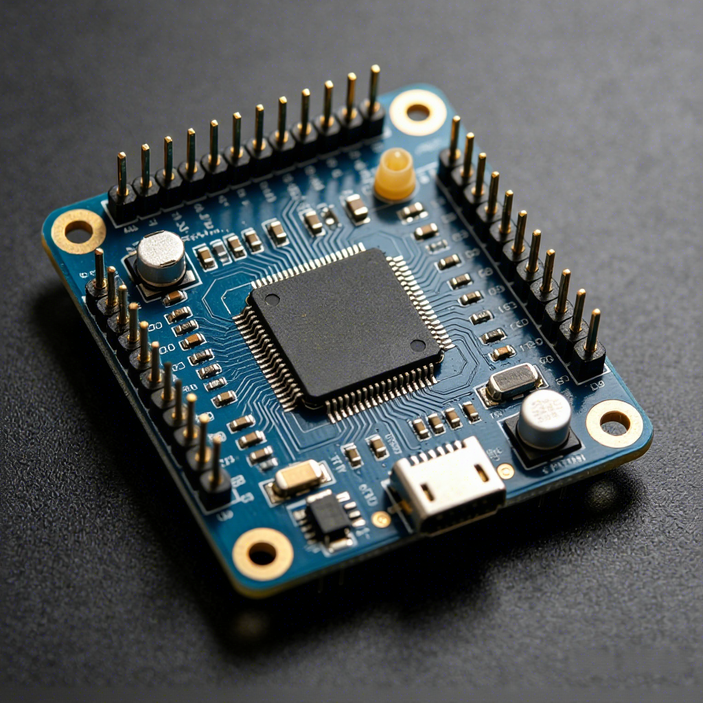
The board and system shown also reflect a prototyping mindset. The PCB includes headers, connectors, and a small-form-factor layout that is convenient for modular wiring and test bench use. The visible setup shows an external power adapter, cabling, and a stereo speaker pair, which makes it easy to picture the board being used in a lab, an engineering desk, or a hobby audio project.
Visible Interface and Functional Layout
Digital input and output structure
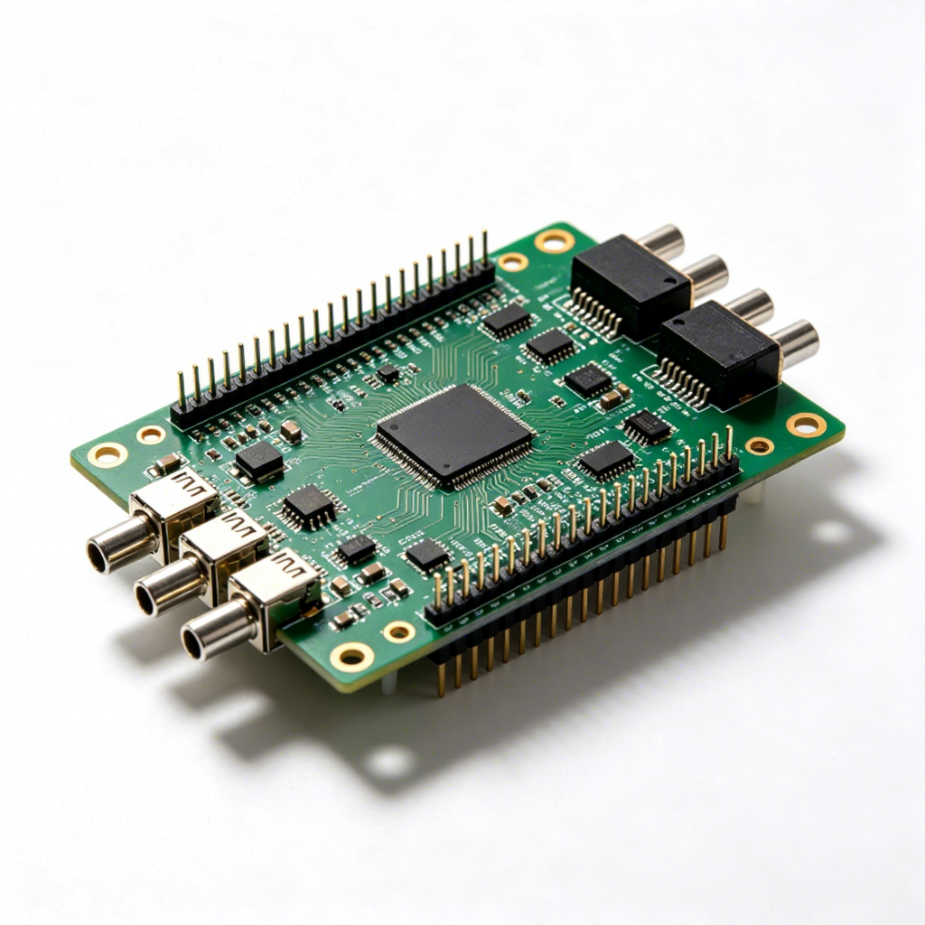
The product image shows HDMI input, optical input, and coaxial input on the audio decoder unit. It also shows RCA outputs labeled for Front, Center, and Rear channels, along with a dedicated subwoofer output. That layout points to a 5.1 channel decoding workflow, where one device receives a digital source and distributes it to a multichannel speaker chain or amplifier system.
USB ports are also visible. Their exact purpose is not confirmed from the image, so they should be treated carefully as interface features rather than assumed playback or firmware functions.
PCB construction
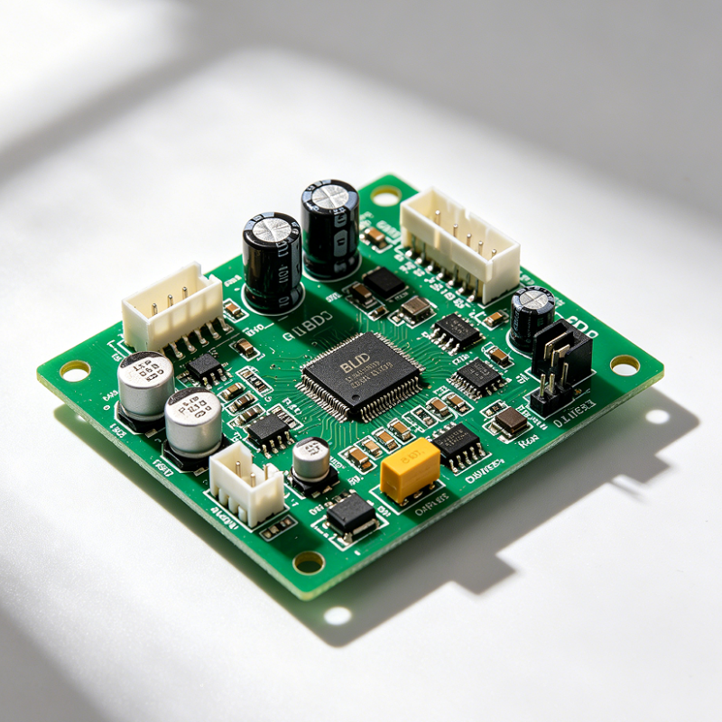
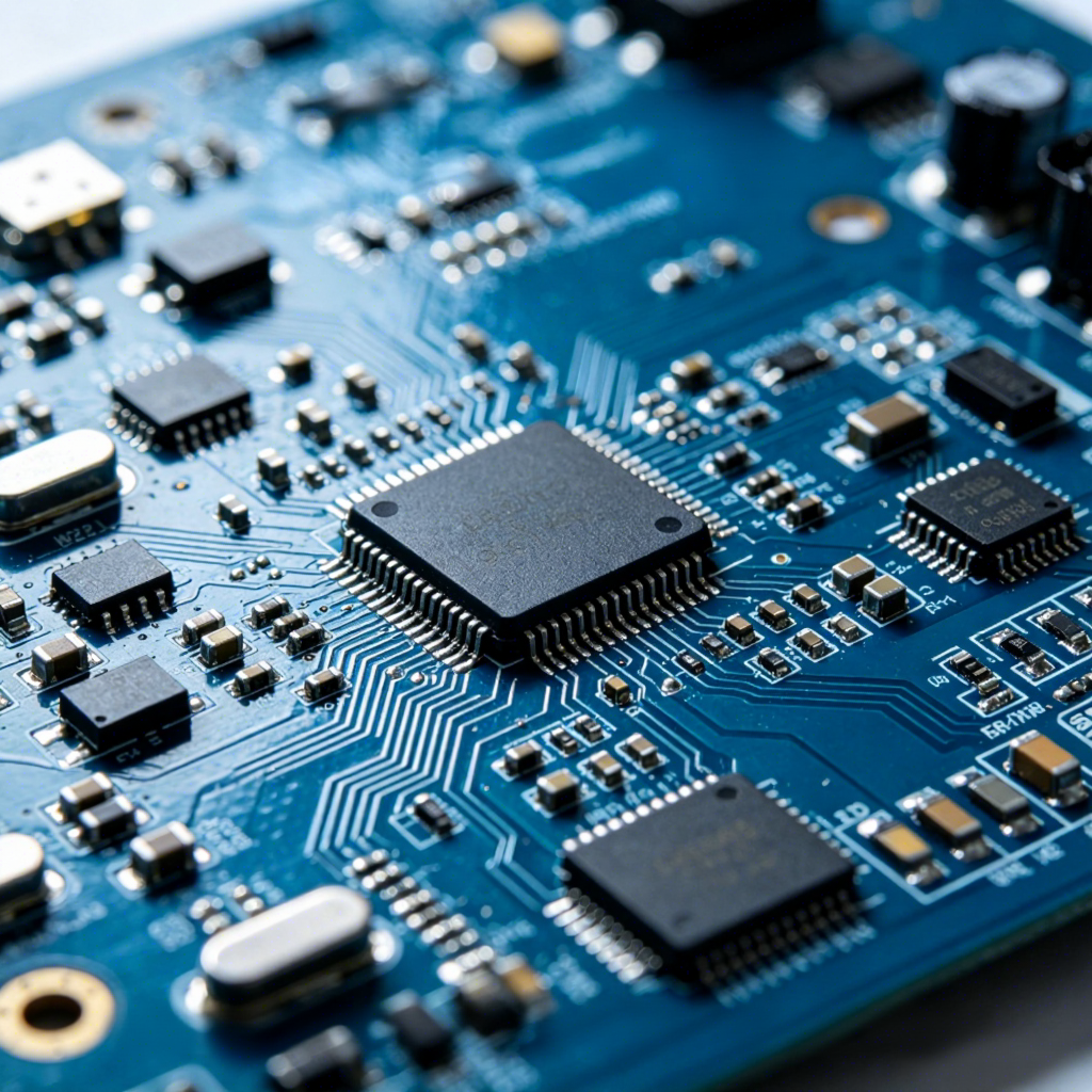
The PCB section appears to use a green solder mask on an FR-4 style substrate, with surface-mount parts, a central controller IC, pin headers, and edge connectors. Another visible board variant shows multiple coaxial RF-style connectors and dual rows of headers, which suggests a modular electronics approach. That configuration is often useful in signal-processing, communication, sensor, or test systems where integration flexibility matters.
Key Specifications and Capabilities
Because the image does not confirm exact chipset or electrical ratings, the safest way to describe the board is by visible capability and architecture:
- Multi-input digital audio interface with HDMI, optical, and coaxial connections
- Multi-channel analog output section for front, center, rear, and subwoofer routing
- Compact enclosure suited to desktop or shelf placement
- External powered setup with visible adapter indicator
- Modular PCB structure with headers and connector ports for integration and wiring
For buyers comparing a DC5V DIY Home Theater Speaker Amplifier PCB Module or a broader Digital Decoding PCB platform, these visible features indicate a board designed around straightforward signal conversion and bench-friendly assembly.
Materials and Finish Options
The visible housing appears to use a silver-gray finish with a dark front or top I/O panel. It likely has either a metal shell or a metal-look surface, though the exact material is not confirmed. The PCB itself is a standard green solder mask board with exposed pads and plated through-holes. Connectors and headers appear to be practical, durable parts chosen for repeated assembly and testing.
For custom builds, buyers may often request different PCB surface finishes, enclosure treatments, connector positions, or labeling layouts. hcdpcba’s PCBA and OEM/ODM capabilities make that type of adaptation more realistic for projects that need a tailored signal path or a branded front panel.
Manufacturing Process and Assembly Flow
This type of board usually follows a standard electronics manufacturing route: PCB fabrication, SMT placement, through-hole assembly where needed, reflow soldering, inspection, and functional testing. For an AC3 Audio Decoder Board or a similar audio interface module, testing typically focuses on connector integrity, power-up behavior, channel routing, and clean signal delivery through the output stage.
hcdpcba also offers DFMA support, which can help refine the board before production starts. For audio products, that can reduce rework around connector placement, grounding layout, assembly access, and enclosure fit.
Application Scenarios
This board is relevant in several settings:
- Home theater integration with legacy 5.1 speaker systems
- TV and media player signal conversion to analog speaker inputs
- Prototype validation for audio firmware and output stages
- Lab demonstrations and bench testing of digital decoding paths
- Hobby electronics projects that require compact signal routing
The second PCB style shown in the preparation data also suggests use in embedded systems, industrial electronics, instrumentation, and modular signal I/O, where coaxial connections and pin-header integration are practical advantages.
Quality Control and Buyer Decision Factors
When selecting an AC3 Audio Decoder Board, buyers usually look past the marketing label and focus on a few concrete points: input compatibility, output mapping, connector robustness, power arrangement, and how easily the module fits into an enclosure or test setup. For engineers, the important question is not just whether the board decodes audio, but whether the physical layout supports stable wiring and repeatable assembly.
Quality control should cover solder joint consistency, connector seating, board flatness, and functional verification across the expected audio path. hcdpcba’s assembly and testing services are relevant here because they support small-batch and large-batch production with process control instead of one-off hand wiring.
Customization Guidance
If you are planning a custom version of this module, start with the interface map. Decide which digital inputs are required, how many analog outputs are needed, where the power entry should sit, and whether the board needs a different enclosure or mounting pattern. For a DC5V DIY Home Theater Speaker Amplifier PCB Module concept, power architecture and output compatibility should be reviewed early so the final system matches the speaker or amplifier stage.
Related keyword references such as AC3 5.1 Surround Digital Audio Decoder Board and Digital Decoding PCB should be used when discussing product families, but the real customization work comes from pinout planning, connector placement, and assembly constraints.
Request a Prototype or Custom Build
For buyers developing audio hardware, the most useful next step is usually a prototype build with clear interface requirements and a defined test plan. hcdpcba can support PCB prototype, SMT assembly, component sourcing, testing, and OEM/ODM workflows for modular electronics projects. If you need a practical AC3 Audio Decoder Board build or a related digital audio module tailored to your system, reach out with your schematic, target connectors, and enclosure constraints so the production path can be matched to your application.
Contact hcdpcba at +86 18924624188 to discuss PCB fabrication, PCBA assembly, and custom audio electronics integration.