Mixed Technology PCBA: SMT and THT Assembly Guide for OEM Buyers
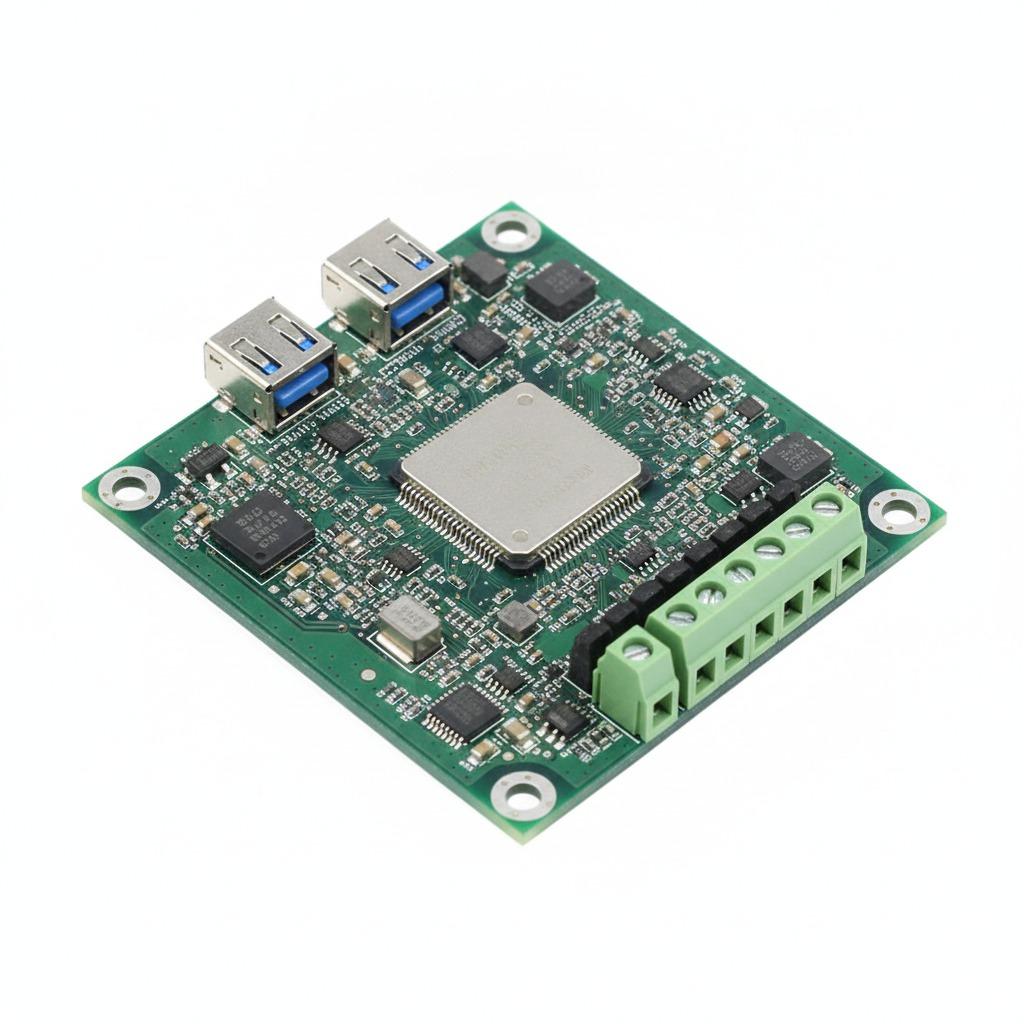
A mixed technology PCBA combines surface-mount technology (SMT) and through-hole technology (THT) on the same printed circuit board assembly. This approach is widely used when a product needs compact, high-density electronics together with larger connectors, relays, transformers, terminal blocks, power components, or other parts that benefit from through-hole mounting.
For OEM buyers, sourcing managers, and hardware engineers, mixed technology PCB assembly creates a different manufacturing challenge from standard SMT-only production. The key question is not simply whether a supplier can place SMT components and solder through-hole parts. Buyers need to understand whether the manufacturer can coordinate SMT assembly, THT insertion, soldering sequence, component sourcing, inspection, testing, and engineering changes as one controlled production process.
Teams that want to understand the SMT portion of the manufacturing workflow first can review the HCDPCBA SMT PCB Circuit Board Assembly Service Guide before evaluating the additional requirements introduced by mixed assembly.
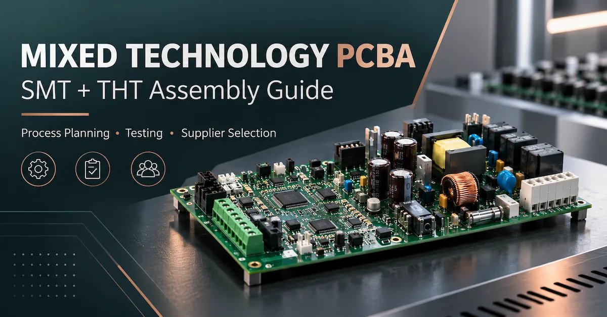
What Is Mixed Technology PCBA?
Mixed technology PCBA refers to a PCB assembly that includes both surface-mount components and through-hole components.
SMT components are mounted directly onto PCB pads and are generally suitable for automated placement, compact layouts, and high component density.
Typical SMT parts include:
- Resistors and capacitors
- Microcontrollers
- Memory
- Sensors
- MOSFETs
- Power-management ICs
- QFN, QFP, BGA, and similar packages
Through-hole components use leads or pins inserted through plated PCB holes.
Typical THT parts include:
- Terminal blocks
- Connectors
- Relays
- Transformers
- Large electrolytic capacitors
- Power inductors
- Switches
- Pin headers
These two assembly methods are often combined because they solve different engineering problems.
SMT supports compact electronic design and efficient automated production, while through-hole mounting can be useful where the product requires larger components, stronger mechanical connections, higher-current interfaces, or components unsuitable for conventional SMT placement.
Mixed Technology PCBA vs High-Mix PCBA
The terms mixed technology PCBA and high-mix PCBA describe two different manufacturing concepts.
Mixed technology refers to the assembly technologies used on one PCB, normally SMT plus THT.
High-mix manufacturing refers to a production environment that handles many different PCB designs, revisions, BOMs, or production quantities.
A project can therefore be:
- Low-volume mixed technology PCBA
- High-volume mixed technology PCBA
- High-mix SMT-only PCBA
- Low-volume high-mix mixed assembly
This distinction matters when selecting a supplier.
Mixed technology creates challenges around soldering sequence, component accessibility, thermal processes, inspection, and secondary assembly.
High-mix manufacturing creates additional challenges around setup changes, BOM control, material management, revision control, and flexible production scheduling.
For projects involving smaller batches, multiple board types, or frequent engineering changes, buyers can also review HCDPCBA's Low-Volume High-Mix PCBA Manufacturing Guide.
Where Is Mixed Technology PCB Assembly Used?
Mixed assembly is useful whenever a PCB needs both dense electronic circuitry and larger mechanical, interface, or power components.
Common application categories include:
Industrial Control Electronics
Industrial control boards may combine processors, communication ICs, sensors, and small passive components with terminal blocks, relays, connectors, and power components.
The SMT portion handles control and signal-processing functions, while THT components provide external connections or support larger electrical loads.
Power Electronics
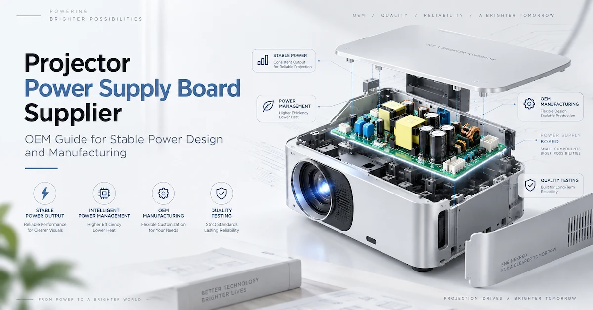
Power supply boards, inverter controllers, charging systems, and power-management electronics may combine compact SMT control circuitry with transformers, inductors, relays, connectors, and large capacitors.
These assemblies often require careful consideration of thermal mass, soldering accessibility, mechanical stability, and component spacing.
IoT and Embedded Equipment
IoT gateways and embedded controllers may contain wireless modules, processors, memory, sensors, and power-management ICs alongside Ethernet connectors, terminal blocks, headers, or DC input connectors.
Smart and Consumer Electronics
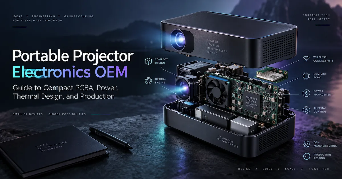
Smart-home controllers, appliances, projectors, security systems, and other connected devices may also use mixed technology PCBA when compact digital electronics must interface with larger power or mechanical components.
The application category alone should not determine the manufacturing process. Buyers should provide the actual board design, BOM, assembly requirements, and testing expectations so the manufacturer can evaluate the project correctly.
Why Is Mixed Technology PCBA More Complex Than SMT-Only Assembly?
A standard SMT assembly can often move through a relatively continuous process:
Solder paste printing → SMT placement → reflow → inspection → testing
Mixed technology PCB assembly normally introduces several additional stages.
A typical workflow may become:
SMT printing → placement → reflow → SMT inspection → THT insertion → secondary soldering → THT inspection → programming/testing
Every additional manufacturing step introduces variables that need to be controlled.
Assembly Sequence Must Be Planned
The manufacturer needs to determine:
- Which components should be installed first?
- Which parts can tolerate reflow?
- When should THT components be inserted?
- Will selective soldering be used?
- Is wave soldering practical?
- Which components require manual soldering?
- Will previously assembled parts be exposed to another thermal cycle?
There is no universal manufacturing sequence for every mixed technology PCBA.
The correct process depends on the PCB layout, component packages, component height, soldering accessibility, thermal sensitivity, manufacturing volume, and final acceptance criteria.
DFMA Is Especially Important for Mixed Assembly
Design for Manufacturing and Assembly should begin before production rather than after defects appear.
For mixed technology PCBA, a DFMA review should examine how the SMT and through-hole portions of the board interact.
Component Spacing
Large components can obstruct:
- Soldering tools
- Selective solder nozzles
- Inspection cameras
- Test probes
- Fixtures
- Rework access
Problem components commonly include:
- Transformers
- Relays
- Large capacitors
- Tall connectors
- Terminal blocks
A small layout adjustment before production may prevent a difficult manual operation later.
Through-Hole Design
Important factors can include:
- Hole size
- Lead diameter
- Pad geometry
- Annular ring
- Copper distribution
- Thermal connections
- Component seating
- Solder accessibility
The objective is not simply to make the component physically fit the board. The joint also needs to be manufactured consistently.
Component Orientation
Polarity and orientation should be clearly documented for components such as:
- Electrolytic capacitors
- LEDs
- Diodes
- Connectors
- Relays
- Switches
Production teams should not have to interpret ambiguous assembly information.
Test Accessibility
Test points and programming interfaces should remain accessible after all SMT and THT components have been installed.
Important interfaces may include:
- Power rails
- Programming headers
- Communication ports
- Diagnostic signals
- Inputs and outputs
HCDPCBA describes DFMA support as part of its broader electronics manufacturing scope alongside SMT assembly, PCB prototyping, component sourcing, assembly, and testing. Buyers can review the company's published manufacturing scope on the HCDPCBA About Us page. hcdpcba.com
Typical Mixed Technology PCBA Manufacturing Process
Although each project needs its own production plan, the following workflow provides a practical framework.
| Stage | Main Purpose | What Buyers Should Confirm |
|---|---|---|
| Engineering review | Identify manufacturability risks | Files, revisions, special requirements |
| BOM review | Confirm components and sourcing scope | MPNs and approved alternatives |
| SMT assembly | Install surface-mount components | Package and placement requirements |
| Reflow | Form SMT solder joints | Process suitability |
| SMT inspection | Identify assembly defects | Required inspection methods |
| THT insertion | Install through-hole components | Orientation and mechanical fit |
| Secondary soldering | Complete THT joints | Selective, wave, or manual process |
| Final inspection | Review completed assembly | Acceptance requirements |
| Programming | Load firmware if required | Version and procedure |
| Functional testing | Verify defined functions | Test method and pass/fail limits |
| Release | Approve production configuration | Controlled revision and documentation |
The important point is that these processes need to operate as one manufacturing system rather than as unrelated services.
For buyers considering a single supplier for PCB sourcing, component procurement, assembly, inspection, and testing, HCDPCBA's Turnkey PCBA Manufacturing Guide explains how those responsibilities can be integrated into a broader production workflow. hcdpcba.com
How Should THT Components Be Soldered?
There is no single soldering method that is best for every mixed technology PCB assembly.
The process should be selected according to PCB layout, THT component distribution, production quantity, adjacent components, and quality requirements.
Selective Soldering
Selective soldering can be useful when through-hole joints are concentrated in specific areas of an otherwise SMT-heavy board.
It allows the soldering process to target designated locations while limiting exposure elsewhere on the assembly.
It may be suitable for components such as:
- Connectors
- Terminal blocks
- Relays
- Pin headers
The PCB layout must still provide suitable access for the process.
Wave Soldering
Wave soldering can be efficient when a board contains a suitable number and arrangement of through-hole joints.
However, engineers need to consider:
- Components on the solder side
- Board layout
- Thermal conditions
- Fixture or pallet requirements
- Component clearance
Manual Soldering
Manual soldering may remain appropriate for:
- Prototype quantities
- Small production batches
- Special components
- Difficult-to-access locations
- Components requiring individual handling
Manual soldering should not automatically be treated as a quality problem.
The important procurement questions are:
Why is manual soldering required? Which joints are manually processed? What workmanship criteria and inspection steps control those joints?
BOM Management Is Critical in Mixed Technology PCBA
Mixed assemblies frequently contain a broader component mix than compact SMT-only boards.
A BOM can combine:
- ICs
- Passive components
- Sensors
- Connectors
- Transformers
- Relays
- Terminal blocks
- Inductors
- Large capacitors
- Mechanical or electromechanical components
These categories create different sourcing risks.
For example, replacing one connector with another may appear acceptable electrically but create problems with:
- Height
- Pin spacing
- Pin length
- Housing geometry
- Locking mechanism
- Current rating
- Mechanical alignment
- Enclosure compatibility
For that reason, approved component alternatives should be controlled rather than introduced automatically based only on availability or unit price.
For repeat production, buyers should control at least:
- PCB revision
- BOM revision
- Manufacturer part numbers
- Approved alternatives
- Assembly drawing revision
- Firmware version
- Programming instructions
- Test requirements
- Label requirements
- Packaging requirements
A turnkey sourcing arrangement can simplify responsibility, but the buyer should still define approval authority for substitutions and engineering changes. HCDPCBA's Turnkey PCBA Manufacturing Guide provides additional context on PCB sourcing, BOM management, SMT/THT assembly, and testing under a consolidated manufacturing model. hcdpcba.com
How Should Mixed Technology PCBA Be Inspected?
Quality control should match the actual failure modes of the assembly.
A mixed technology board normally requires more than one inspection method because SMT and THT components create different risks.
SMT Inspection
Depending on the project, inspection may include:
- Visual inspection
- SPI
- AOI
- X-Ray for appropriate hidden-joint components
AOI can help identify visible component and soldering conditions.
X-Ray can support inspection of selected solder joints that cannot be directly seen, such as BGA connections.
However, neither AOI nor X-Ray should be treated as a replacement for functional testing.
Through-Hole Inspection
The THT portion may need inspection for:
- Incorrect orientation
- Poor component seating
- Bridging
- Insufficient solder
- Excess solder
- Lead problems
- Alignment issues
- Inconsistent solder joints
The actual acceptance criteria should be agreed before production.
Functional Testing
Visual inspection tells buyers whether the assembly appears to have been manufactured correctly.
It does not prove that the board performs its intended electronic function.
A functional test may therefore verify:
- Power-up behavior
- Required voltages
- Communication interfaces
- Inputs and outputs
- Relays
- Sensors
- Programming
- Firmware boot
- Product-specific functions
The test plan should identify what is tested and what constitutes a pass.
Simply writing “functional test included” in an RFQ leaves too much room for interpretation.
Mixed Technology PCBA vs SMT-Only PCBA
| Factor | SMT-Only PCBA | Mixed Technology PCBA |
|---|---|---|
| Assembly technology | Mainly SMT | SMT + THT |
| Main solder process | Reflow | Reflow plus secondary soldering |
| THT insertion | Normally none | Required |
| Process stages | Fewer | More |
| Manual handling | Usually lower | Often higher |
| Mechanical components | Less common | Frequently present |
| Selective/wave solder | Usually unnecessary | May be required |
| DFMA complexity | High | Often higher |
| Inspection planning | SMT focused | SMT + THT |
| Cost structure | Placement, packages, test | SMT factors + THT labor/process |
This is why buyers should avoid comparing mixed assembly quotations with SMT-only projects using only a board-level unit price.
What Determines Mixed Technology PCBA Cost?
There is no meaningful universal price for a custom mixed technology PCBA.
Cost depends on the exact design and manufacturing scope.
SMT Complexity
Factors can include:
- Number of placements
- Package types
- Fine-pitch components
- BGA or QFN content
- Double-sided assembly
- Board panelization
THT Complexity
Cost may also depend on:
- Number of through-hole components
- Manual insertion time
- Component preparation
- Connector geometry
- Selective soldering requirements
- Wave soldering requirements
- Manual soldering requirements
Component Cost
The BOM can represent a significant share of total PCBA cost.
Pricing also depends on:
- Component availability
- Minimum order quantities
- Lead times
- Approved brands
- Approved alternatives
Tooling and Fixtures
A project may require:
- Soldering fixtures
- Test fixtures
- Programming fixtures
- Assembly jigs
- Custom pallets
These costs should be separated from recurring production costs when comparing suppliers.
Testing Scope
A basic electrical check and a complete functional test can have very different time and fixture requirements.
For accurate supplier comparison, every quotation should use the same testing definition.
Prototype, Pilot, and Production Require Different Priorities
Mixed technology projects should normally progress through controlled stages rather than treating the first successful prototype as proof of production readiness.
Prototype Stage
The objective is mainly to confirm:
- Basic manufacturability
- Component fit
- Initial functionality
- Programming
- Mechanical interfaces
- Design assumptions
Pilot Production
The pilot stage should focus more heavily on manufacturing repeatability.
Evaluate:
- Assembly sequence
- THT insertion
- Secondary soldering
- Inspection
- Fixture access
- Rework points
- Test time
- Work instructions
- Material control
Repeat Production
Before recurring manufacturing begins, the approved production configuration should be controlled.
This can include:
- Released PCB revision
- Approved BOM
- Approved alternatives
- Firmware version
- Programming method
- Assembly instructions
- Test limits
- Inspection criteria
- Packaging instructions
Buyers working with multiple designs, small production runs, or frequent revisions may also benefit from HCDPCBA's discussion of low-volume high-mix PCBA manufacturing, where production flexibility and change control become especially important. hcdpcba.com
How to Evaluate a Mixed Technology PCBA Manufacturer
A supplier evaluation should go beyond asking:
“Do you support SMT and DIP assembly?”
Instead, ask how the supplier plans to manufacture your specific board.
Can the supplier review the design before production?
The manufacturer should be able to identify major manufacturability questions before production begins.
Which soldering process will be used for the THT components?
Ask whether the plan involves:
- Selective soldering
- Wave soldering
- Manual soldering
- Multiple processes
The answer should be connected to your PCB design rather than given as a generic factory capability.
How are component substitutions managed?
Ask:
- Who proposes an alternative?
- Who approves it?
- What information is compared?
- How is the approved change recorded?
How is each part of the assembly inspected?
Do not evaluate quality based only on the presence of AOI or X-Ray equipment.
Ask which method applies to which assembly risk.
What is included in functional testing?
Confirm:
- Test points
- Interfaces
- Firmware
- Fixtures
- Electrical limits
- Pass/fail criteria
- Required records
How are engineering revisions controlled?
Ask how the supplier distinguishes:
- PCB revisions
- BOM revisions
- Firmware revisions
- Assembly instructions
- Test procedures
This becomes especially important on repeat orders.
What is included in the quotation?
Confirm whether the quotation covers:
- PCB fabrication
- Components
- SMT assembly
- THT insertion
- Secondary soldering
- Programming
- Inspection
- Functional testing
- Fixtures
- Final assembly
- Packaging
Two suppliers can quote very different prices simply because they are quoting different scopes.
HCDPCBA's published manufacturing scope includes SMT assembly, PCBA manufacturing, prototyping, component sourcing, DFMA, testing, and OEM/ODM support. Buyers should turn these general capabilities into a written project-specific scope before comparing quotations. Review HCDPCBA's manufacturing capabilities. hcdpcba.com
What Should Be Included in a Mixed Technology PCBA RFQ?
A complete RFQ helps the manufacturer understand the actual production responsibility and makes supplier quotations easier to compare.
PCB Manufacturing Files
Provide:
- Gerber files
- Drill data
- Fabrication drawing
- Stack-up requirements where applicable
- Board dimensions
- Panelization requirements
BOM Information
Include:
- Manufacturer
- Manufacturer part number
- Quantity
- Reference designator
- Approved alternatives
- Customer-supplied parts where applicable
Assembly Files
Provide:
- Pick-and-place/CPL data
- Assembly drawings
- Polarity information
- THT requirements
- Special soldering requirements
- Mechanical information where necessary
Programming and Test Information
Include where applicable:
- Firmware
- Firmware revision
- Programming instructions
- Test procedure
- Test limits
- Required interfaces
- Test fixture information
Commercial Requirements
Provide:
- Prototype quantity
- Pilot quantity
- Expected repeat-order quantity
- Packaging requirements
- Target delivery expectations
Instead of sending only:
“Please quote 500 PCBAs.”
A more useful request would be:
“We require a mixed technology PCBA with SMT devices and through-hole connectors, relays, and terminal blocks. Please review the Gerber, BOM, CPL, assembly drawing, quantities, and test requirements and confirm the recommended SMT/THT process, inspection plan, testing scope, and quotation exclusions.”
This gives the supplier enough information to evaluate the manufacturing process rather than simply estimating a board price.
Once the production package is prepared, buyers can use the HCDPCBA Contact Us page to submit project requirements for review.
Frequently Asked Questions About Mixed Technology PCBA
What is mixed technology PCBA?
Mixed technology PCBA is a PCB assembly containing both surface-mount and through-hole components. It therefore requires coordination between SMT assembly and one or more THT insertion and soldering processes.
Why combine SMT and through-hole components?
SMT is useful for compact, high-density circuitry, while through-hole assembly may be preferred for larger connectors, relays, transformers, terminal blocks, or mechanically demanding components.
Is mixed technology PCBA more expensive than SMT-only assembly?
It can require more process steps, labor, fixtures, soldering, and inspection. Actual cost depends on the board design, BOM, assembly quantity, soldering method, and testing scope.
Is selective soldering always necessary?
No. The THT portion may use selective soldering, wave soldering, manual soldering, or a combination depending on the board design and production requirements.
Can mixed technology PCBA support low-volume production?
Yes. Mixed technology can be used in prototypes, small batches, pilot production, and higher-volume programs. Low-volume projects often place greater emphasis on engineering flexibility and revision control.
What files are required for quotation?
A useful RFQ normally includes Gerber files, BOM, Pick-and-Place data, assembly drawings, quantities, and test requirements. Programming files should also be supplied when firmware loading is required.
Does AOI verify the complete board?
No. AOI is an inspection method for visible assembly conditions. It should not be treated as proof that every electrical and functional requirement has been verified.
Does X-Ray replace functional testing?
No. X-Ray can help inspect selected hidden solder joints, but it does not verify complete board functionality.
When should DFMA be performed?
Ideally before the first manufacturing build. Early DFMA can identify spacing, component, soldering, fixture, assembly, and testing problems before they become production issues.
How should buyers compare mixed technology PCBA suppliers?
Compare the complete scope, including engineering support, PCB sourcing, BOM control, SMT assembly, THT processing, inspection, functional testing, change control, and prototype-to-production support—not only the quoted unit price.
Conclusion
A successful mixed technology PCBA project depends on more than combining SMT and through-hole components on the same board. The real manufacturing challenge is coordinating component sourcing, assembly sequence, reflow, THT insertion, secondary soldering, inspection, programming, testing, and revision control as one repeatable production process.
For OEM buyers and engineering teams, supplier selection should therefore focus on manufacturing responsibility and process control rather than equipment lists or the lowest unit quotation. Before approving a supplier, define the PCB revision, BOM, approved component alternatives, SMT and THT requirements, soldering method, firmware, inspection criteria, functional-test limits, production quantities, and packaging expectations.
A detailed RFQ gives the manufacturer enough information to identify risks before production and makes quotations from different suppliers more comparable. Buyers planning a project can first review HCDPCBA's turnkey PCBA manufacturing process and manufacturing capabilities, then submit Gerber files, BOM data, quantities, assembly requirements, and testing expectations through the HCDPCBA Contact Us page for a project-specific manufacturing review.