What a multi usb type‑c fast charging pcba is really for
A multi usb type‑c fast charging pcba is the kind of board buyers look at when they need to turn a battery cell or battery pack into a usable portable charging product. In plain terms, it is the control and interface layer between the cell and the outside world: it helps manage charging, discharging, port output, and status indication. For sourcing teams and product engineers, the question is rarely whether the board “looks right.” The real question is whether the board architecture fits the product you are building, whether the assembly is robust enough for production, and whether the supplier can deliver repeatable PCB assembly rather than a one-off sample that only works on the bench.
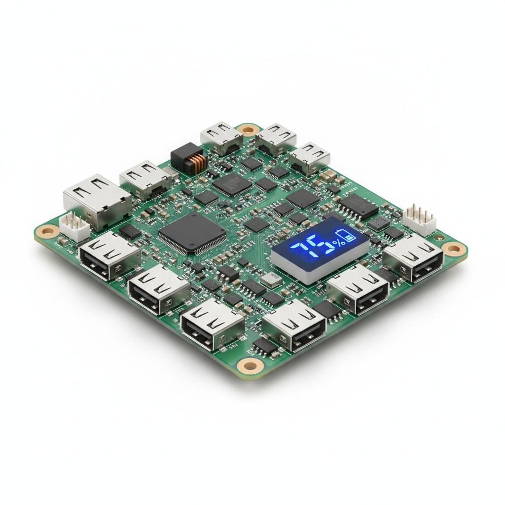
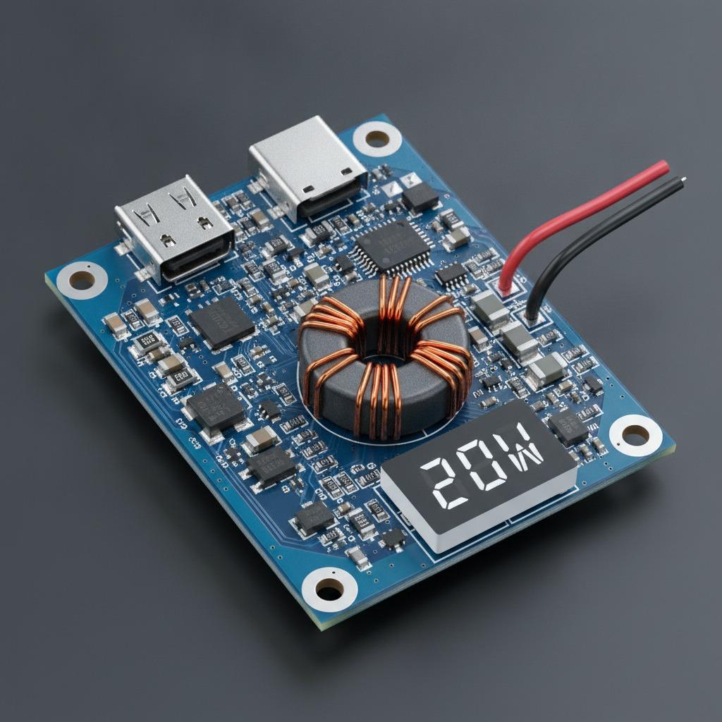
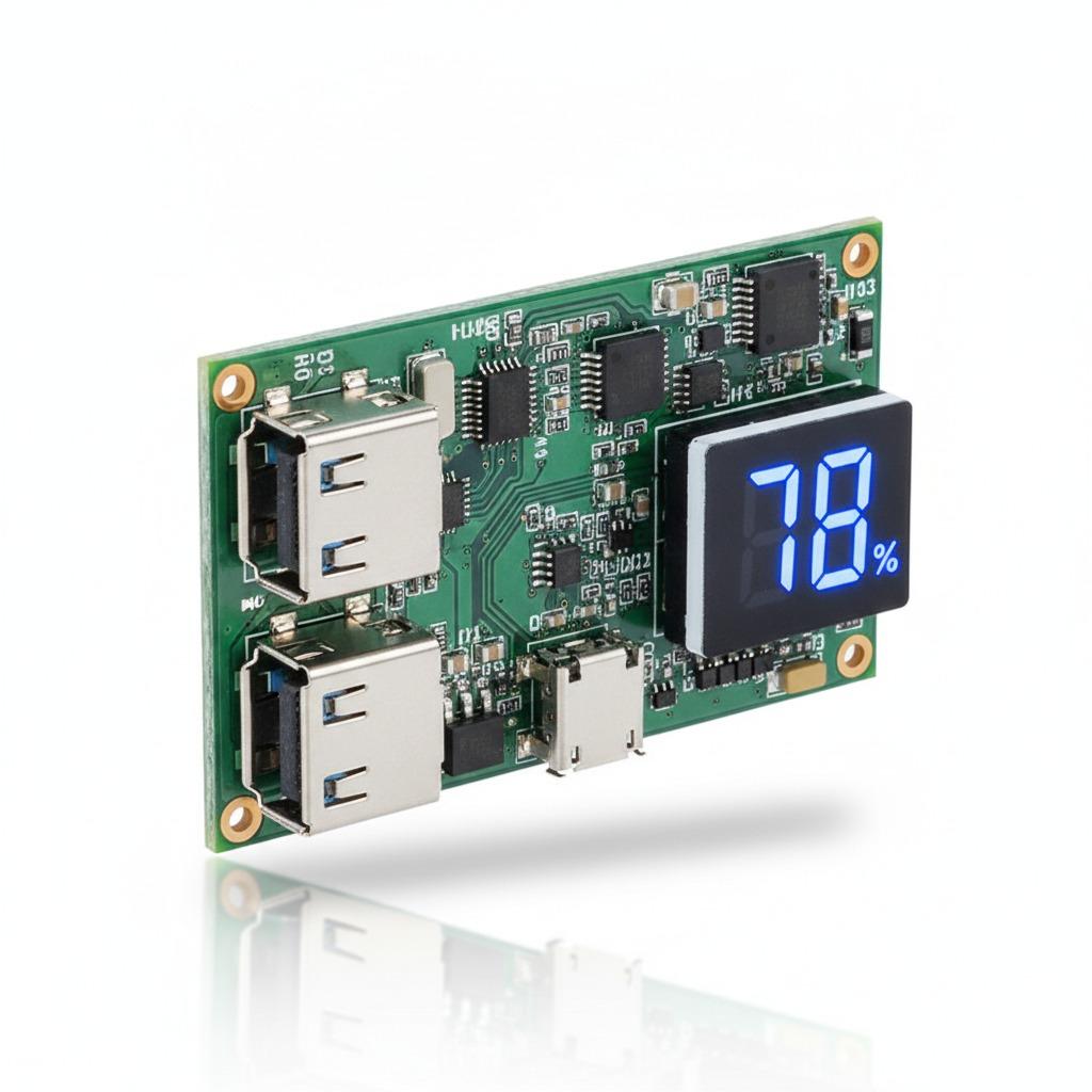
The boards shown in the preparation data appear to be compact power bank controller modules with multiple USB interfaces, including USB-A, USB-C, and in some versions micro-USB, plus a small digital display. That combination is common in consumer portable chargers, DIY battery packs, and OEM replacement modules. It also means the buyer needs to think beyond connectors. Port count, display behavior, protection logic, and mechanical fit all matter, and those details are not always obvious from a product photo.
Key features buyers usually check first
When people evaluate a power bank PCB assembly, they often start with the visible features: port types, indicator style, and board layout. That is sensible, but it is only the opening step. A board with dual USB-A outputs and a numeric display may suit a simple consumer power bank, while a design with USB-C and micro-USB can be better for mixed-input or mixed-output product concepts. The visible metal connector housings, mounting holes, and elongated board shape also suggest the module is meant to be integrated into a defined enclosure, not left floating inside a case.
One practical note: a display adds user value, but it also adds another part that must survive soldering, handling, and vibration. If a supplier offers led digital display power bank pcba units, ask how the display is mounted, whether the board has any strain relief, and how the assembly is tested. The smallest mechanical weakness can become the largest warranty issue later.
What the image seems to show
The visible modules include green solder-mask PCBs, surface-mount components, through-hole connector soldering, and test pads. Polarity markings such as B+ are visible, which is useful for assembly and rework. Marketing badges in the graphic mention CE and RoHS, but those should be treated as supplier claims unless the documentation is provided separately. That distinction matters, especially for brands preparing for retail or export channels.
How these modules fit into production
From a manufacturing standpoint, this is not just a “board.” It is a small electronics system that depends on PCB fabrication, SMT placement, connector soldering, and functional testing. In many cases, the buyer wants a ready-to-integrate power bank control module that can move quickly into enclosure assembly. That is where working with a supplier that offers both PCB assembly and test support becomes useful.
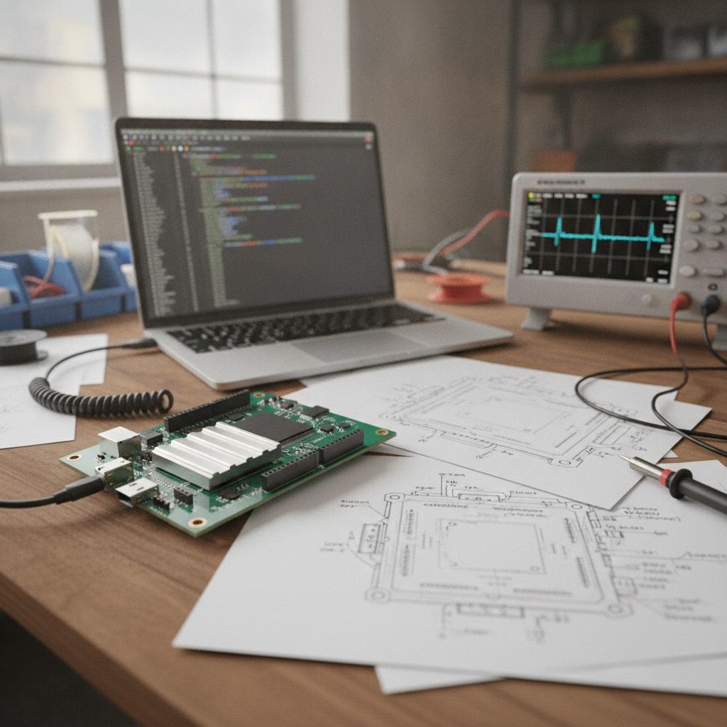
hcdpcba, for example, presents itself as a provider of SMT贴片, PCB打样, 元器件代采, 组装, 测试, DFMA services, and OEM/ODM support. For engineers, that combination is more valuable than a generic price quote. It means the supply chain can be discussed as a process: prototype the board, place parts, assemble connectors, test the finished unit, then adjust the layout if the design is awkward to build. In practice, this is how many portable charging projects move from sample to production without repeated surprises.
Why DFMA matters here
For a compact charging board, design for manufacturability and assembly is not a buzzword. If port spacing is too tight, if the display is hard to align, or if lead wires interfere with the enclosure, production speed slows down and defect rates rise. A good DFMA review can catch those issues before the first bulk order.
Selection criteria that save time later
Choosing a power bank control board should be a fit-check exercise, not a guess. Start with the product concept, then work backward to the electronics. If your device needs multiple ports, confirm the port mix. If the user needs visible battery status, confirm the display format. If the enclosure is slim, confirm connector height and board length. If the product will be mass assembled, confirm soldering method and test access.
For a CE RoHS power bank pcba, buyers often assume the compliance work is already solved. That is a mistake. You still need to verify the paperwork, the scope of the claim, and whether the finished product configuration is the same one that was evaluated. A board alone does not make a compliant product. The battery, enclosure, wiring, and final assembly all matter.
Common mistakes buyers make
The biggest mistake is buying on port count alone. A second mistake is assuming that any board with a USB-C receptacle automatically supports the charging behavior the end customer expects. Fast-charging support is not visible in the photo, and it should not be inferred. Another frequent issue is ignoring mechanical integration. A board can be electrically fine and still fail in production because the mounting holes do not match the enclosure or the display window is misplaced by a few millimeters.
Another quiet risk is underestimating verification. If you are sourcing a power bank pcb assembly for a branded product, ask for assembly process details, test flow, and traceability where available. The cheapest quote is often the most expensive path once rework and returns are counted.
Practical buyer advice for OEM and ODM projects
If you are building a custom portable charger, the board supplier should be part electronics partner, part production planner. Share the enclosure drawing, battery pack configuration, target ports, and user interface expectations early. That gives the factory room to advise on connector placement, component spacing, and any obvious manufacturing risk.
For OEM and ODM projects, the best outcome is usually a board that is boring in production and clear in use. The user sees a stable display and reliable charging ports. The factory sees an assembly that solders cleanly, tests quickly, and fits the housing without force. That balance is what separates a workable charging module from a board that keeps causing exceptions on the line.
FAQ
Can I use this type of board for a DIY battery pack?
Yes, that is one of the common use cases, provided the board matches your battery configuration and mechanical layout. Do not assume compatibility from appearance alone.
Does a visible USB-C port mean true fast charging?
Not necessarily. The presence of USB-C is only a hardware clue. The actual charging behavior depends on the circuit design and component selection, which are not confirmed by the image.
Is the display useful in production?
Usually yes, because it gives the user visible status feedback. Just keep in mind that any extra module adds assembly and test considerations.
What to ask before placing an order
Ask for the board schematic or at least a functional description, the assembly process, the test method, and the exact version of the module you are buying. If the supplier offers component sourcing, assembly, and testing in one place, that can shorten lead time and reduce finger-pointing between vendors. For teams comparing suppliers, this is often the deciding factor.
If you are planning a custom power bank controller board or want to adapt an existing module for your enclosure, a practical next step is to send your requirement set, battery pack outline, and port layout to the assembler early. With the right PCB fabrication and PCB assembly partner, the project is much easier to control before it reaches bulk production.