Why a PD20W pcba deserves more attention than it gets
A PD20W pcba may look like a small USB board, but in practice it sits at the point where product reliability, charging behavior, and user experience either come together or fall apart. For engineers and sourcing teams, the real question is not whether the board can fit inside a compact enclosure. The question is whether the circuit can deliver stable power, survive repeated plug cycles, and be built consistently at scale.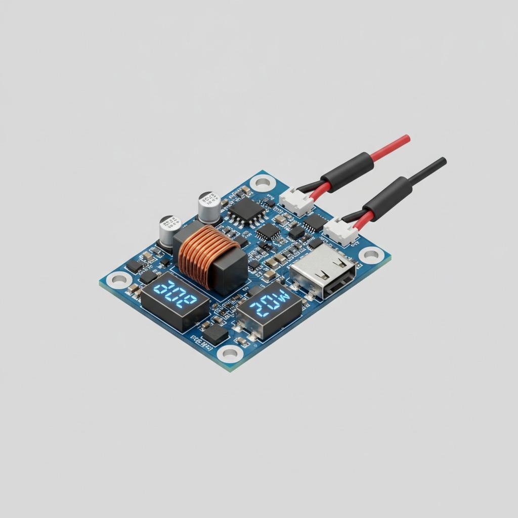
That matters because USB power modules are often treated as commodity parts. They are not. A poorly assembled power bank circuit board or power bank motherboard can create noisy output, weak contact at the connectors, unstable display behavior, or heat concentration around the switching stage. On a bench, those problems are annoying. In a shipped product, they become returns.
What the board image tells a buyer
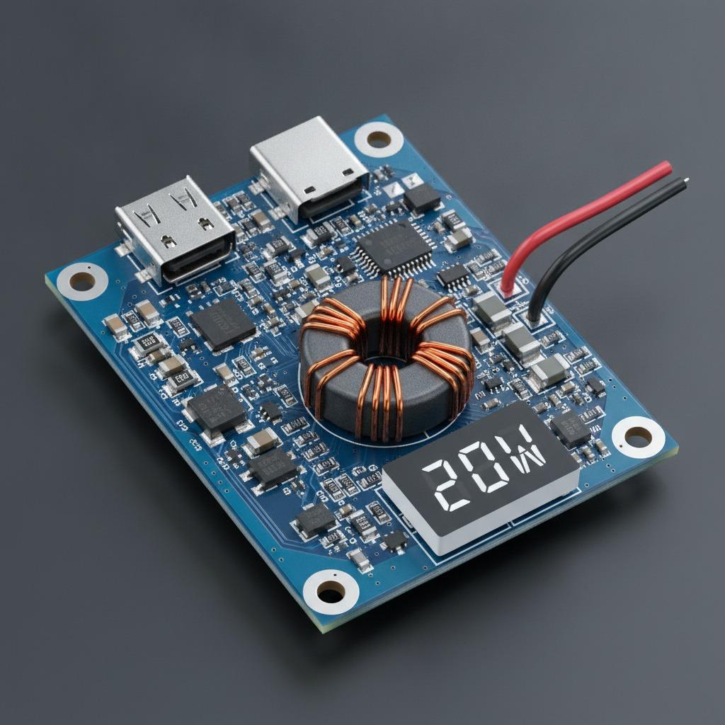
The board shown is a compact blue FR-4 assembly with dense surface-mount components, a visible inductor, a small numeric display, multiple USB interfaces, and red/black lead wires attached with strain relief. It also has mounting holes, which is a practical detail that often gets overlooked until enclosure design is already locked.
From the visible layout, this is best understood as a USB-based power electronics module rather than a bare interface card. The exact circuit purpose is not fully identifiable from the image alone, and that caution matters. It could function as a charger-discharge board, a DC-DC converter, or another small power supply module. What can be said with confidence is that the design is meant to route, regulate, and present power through USB connectors and wired terminals.
For buyers, those visual clues suggest three priorities: connector durability, thermal management, and assembly quality around the power stage.
Where these modules are commonly used
Boards like this appear in DIY power packs, field test fixtures, repair builds, portable devices, and embedded systems that need more than one USB output. A small display is often useful for status feedback or rough voltage reading. Multiple ports make the module more flexible, especially when a prototype needs to serve as both a user-facing charging interface and an internal power node.
That flexibility is why sourcing decisions should be more careful than they often are. A buyer may only see a compact board with a couple of USB-A ports and a USB-C connector, but the actual demand on the circuit can vary a lot depending on the use case. A lab prototype has different tolerance for quirks than a consumer-facing product.
What to check before placing an order
The first thing to confirm is the intended function. Is the board a charger, a boost converter, a battery management-related module, or a general power bank circuit board? If the answer is vague, the procurement risk goes up immediately. Do not assume every board with a display and USB ports supports the same operating modes.
Next, review the assembly approach. A board with dense SMT parts, a copper-wound inductor, connector shells, and soldered wires depends on good process control. Connector placement, solder joint wetting, and pad design all affect field durability. If the product will see frequent cable insertion, the solder anchoring around the USB receptacles becomes more important than a casual photo review would suggest.
Also look at the board outline and mounting strategy. A compact power bank motherboard with mounting holes is easier to integrate cleanly, but only if the holes, port positions, and wire exits are aligned with the enclosure and the internal cable path. A nice electrical design can still become a mechanical headache if those details are left to late-stage guessing.
Selection criteria that are worth the time
If you are comparing suppliers or revisions, ask for the things that affect manufacturability, not just the marketing layer. DFMA feedback is useful here because it can flag connector spacing, assembly access, and rework risk before tooling is frozen. For this type of board, that matters more than cosmetic polish.
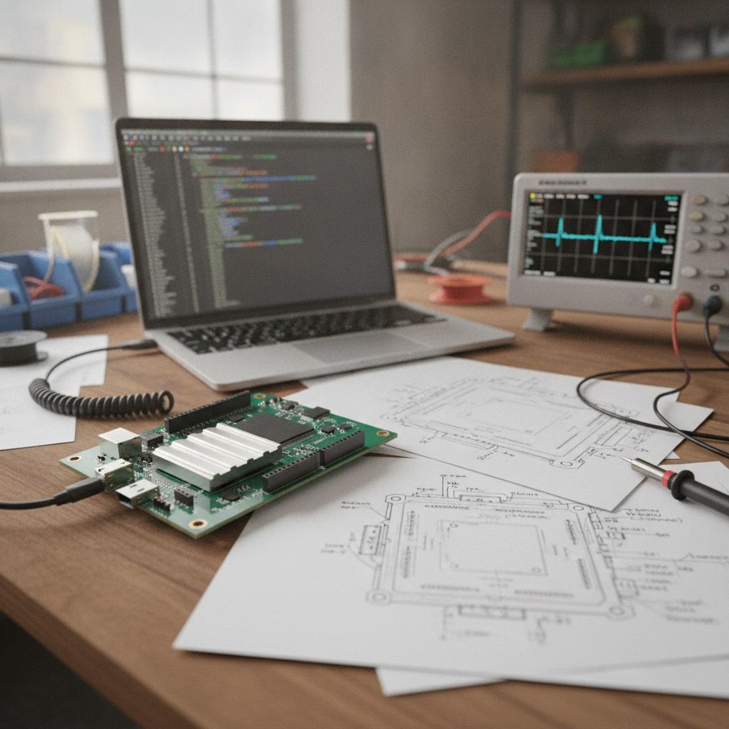
You should also ask how testing is handled. A practical test plan for a power supply module usually checks power-up behavior, connector continuity, and whether the display or control section behaves consistently after assembly. No one should promise exact performance without validated data, but a supplier should still be able to describe how boards are checked before shipment.
Common mistakes buyers make
One common mistake is assuming a power module is simple because the bill of materials looks short. In reality, the weak points are often in assembly, not component count. A small failure at the USB connector or around the switching section can ruin the whole board.
Another mistake is treating all USB ports as interchangeable. A board may show USB-A and USB-C receptacles, but that does not tell you how power is routed, whether the ports are input or output, or what logic governs them. That distinction needs to be confirmed early, especially if the module is going into a battery pack or shared charging system.
A final mistake is skipping thermal thinking. Compact boards with power conversion hardware can concentrate heat around the inductor, control ICs, and electrolytic capacitor area. If the enclosure is tight, or airflow is poor, the design should be reviewed with that in mind before mass production begins.
Why manufacturing capability matters here
For this kind of product, PCB fabrication is only half the story. The other half is disciplined SMT贴片, careful connector soldering, and enough process control to keep units consistent from batch to batch. hcdpcba positions itself around that exact workflow: PCB打样, SMT贴片, 元器件代采, 组装, 测试, plus DFMA support when a design needs to be made easier to build.
That combination is especially useful for USB-based modules because these boards often move from prototype to small-batch production quickly. The design may start as a lab prototype, then become part of a portable product or a repair platform. At that stage, cheap shortcuts become expensive. A board that looked acceptable in a one-off build may not survive repeated use unless the assembly process is controlled.
Practical buyer advice
If you are sourcing a board like this, ask for clear confirmation of the port function, the power path, and the intended operating scenario. Request assembly details for the USB connectors and lead-wire attachment. If the board is going into a product, ask for a review of the mechanical fit before committing to quantity.
For projects that need custom power behavior, OEM and ODM support can be more valuable than a finished off-the-shelf module, because the board can be adapted to the enclosure, display needs, and wiring constraints instead of forcing the product team to work around them.
FAQ
Is this board definitely a power bank controller?
Not definitely. It appears to be a USB-based power module, but the exact function is not fully identifiable from the image alone.
Why is the display important?
A display gives the user or technician a quick read on status, and that is helpful in portable power or test applications. It also helps during debugging.
What should I ask a supplier before buying?
Ask about PCB fabrication, SMT assembly, wire attachment, testing, and whether the design can be adjusted through DFMA if needed.
Next step
If you are building a USB power module, a battery-backed accessory, or a compact charger/discharge assembly, it is worth discussing the board early instead of trying to fix manufacturing issues later. hcdpcba can support PCB打样, SMT贴片, 元器件代采, 组装, 测试, and custom OEM or ODM work. For a direct conversation, call +86 18924624188 and start with the simplest question: what exactly does the board need to do in your product, and what will it take to build it reliably?