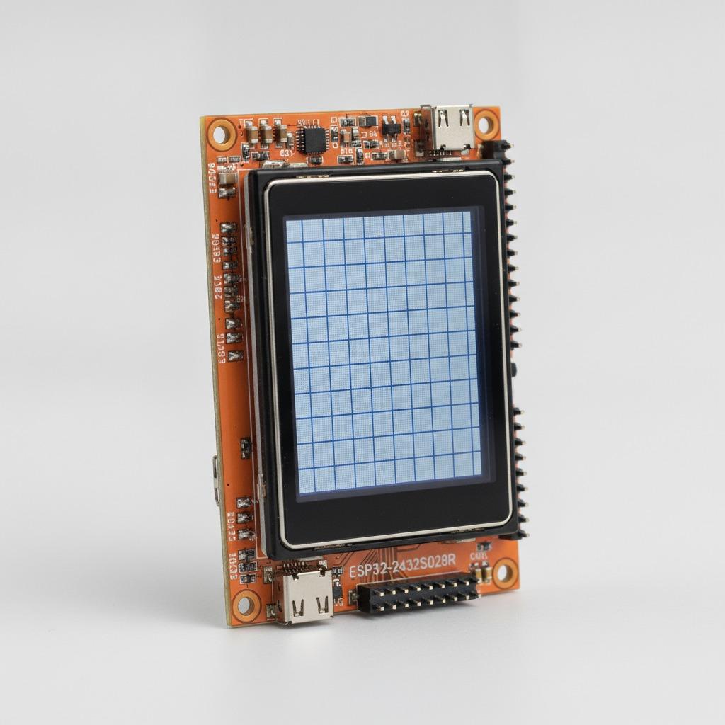
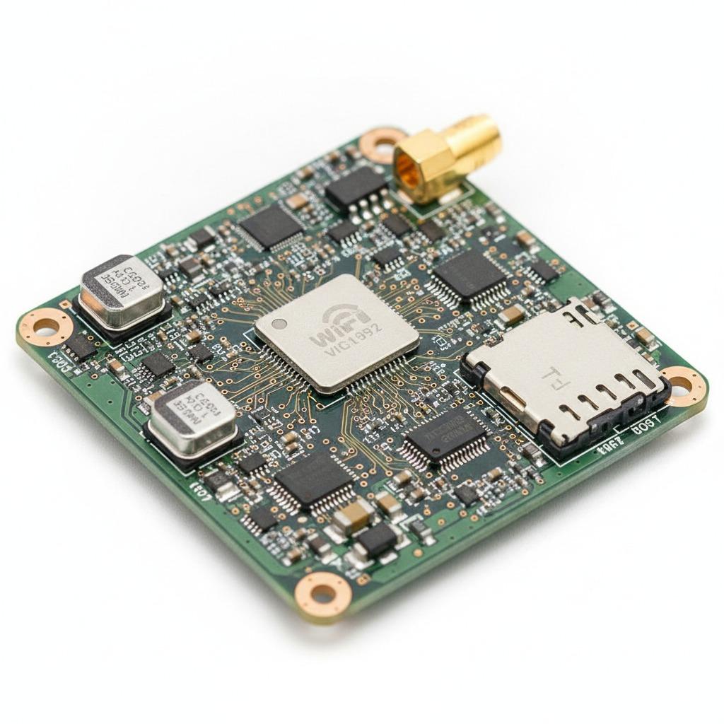
What a BLDC ceiling fan PCB is really responsible for
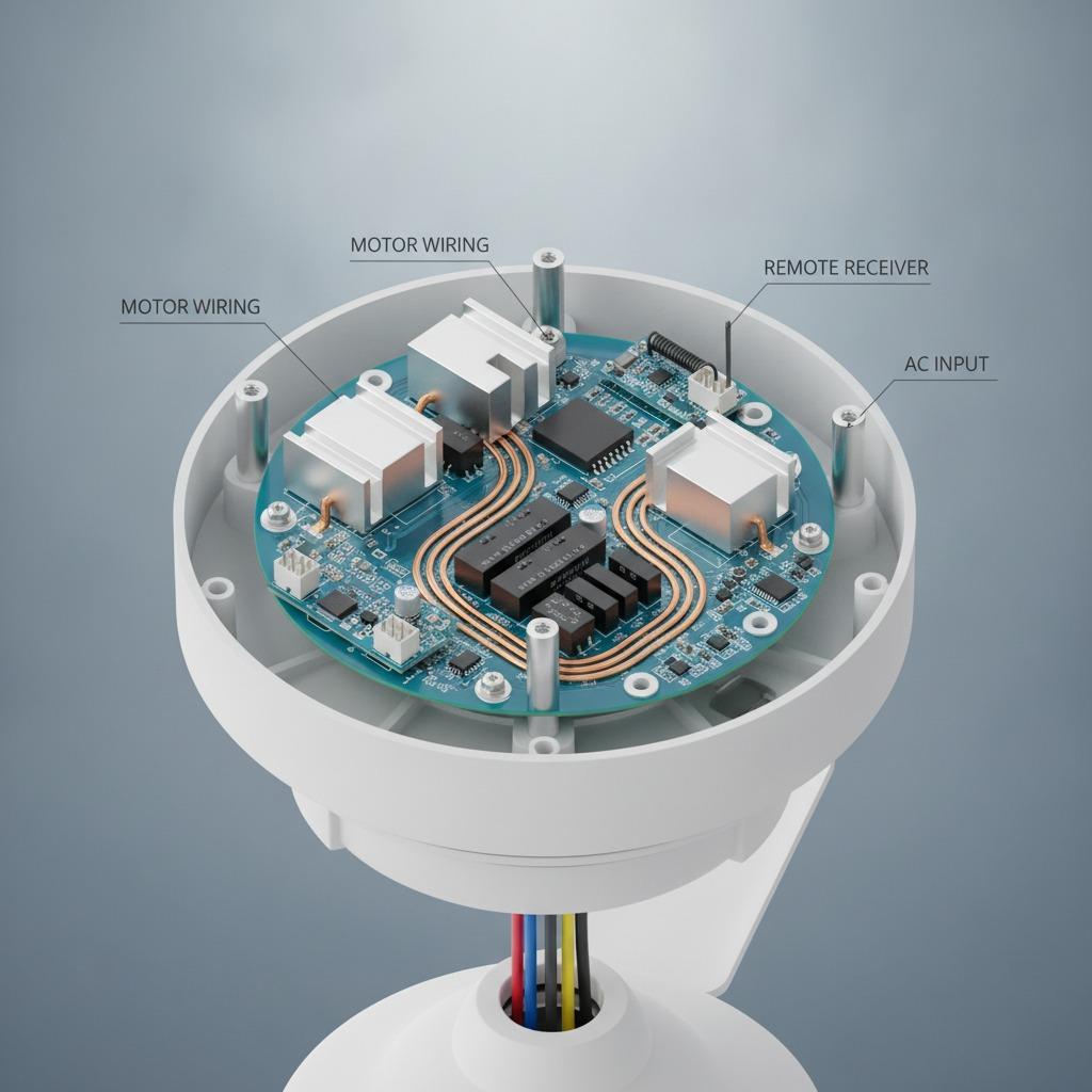
A BLDC ceiling fan PCB is not just a small control board tucked inside the canopy. It is the part that translates user commands into motor behavior, manages power flow, and keeps the fan responsive when a homeowner changes speed, direction, or lighting mode. For sourcing teams and product engineers, that means the board sits at the center of performance, reliability, and cost.
In practice, the PCB may be asked to do more than a conventional fan board ever did. It can support soft-start behavior, quiet speed changes, remote control input, energy-efficient operation, and sometimes integration with smart-home features. That is why teams comparing a BLDC fan driver PCB with a basic AC fan controller should not treat them as interchangeable. The motor architecture is different, the electronics are more sensitive, and the test burden is usually higher.
Why this board matters to product decisions
For buyers, the main question is rarely “Can it switch the fan on?” It is whether the controller will hold up across long duty cycles, low-voltage variations, and real-world installation conditions. Ceiling fans live in environments where heat, vibration, dust, and inconsistent wiring are ordinary, not exceptional. A weak brushless DC fan circuit board can lead to noisy speed control, unstable startup, shortened service life, or warranty complaints that are expensive to diagnose after shipment.
For product teams, the board also affects the overall industrial design. Smaller housings, quieter operation, lower standby power, and remote or smart control all place demands on layout, component selection, and assembly quality. If the PCB is late or difficult to build, the rest of the program feels it immediately.
Quick comparison: what buyers usually evaluate
When evaluating a ceiling fan controller PCB, the useful comparison is not just price. It is a mix of electrical fit, manufacturability, and support.
Control function: Does the board support the intended speed range, direction control, and remote behavior?
Integration: Can the design work with the chosen motor, receiver, and any lighting module?
Manufacturability: Is the layout practical for SMT assembly, inspection, and testing?
Reliability: Are thermal management, component derating, and protection features adequate?
Supply chain: Can the assembler help source parts and keep the build consistent?
Key design points for a BLDC fan driver PCB
BLDC control is usually more demanding than a simple switched load because the board must manage motor commutation and feedback-related behavior in a stable way. The exact implementation depends on the motor and system design, but several themes come up repeatedly.
Power handling and thermal layout
Even a compact ceiling fan controller PCB can see meaningful thermal stress around power devices and regulators. Copper distribution, trace width, via placement, and component spacing matter. Small layout shortcuts often show up later as heat soak or long-term instability.
Noise, interference, and user experience
Because the fan sits in a home or office environment, electrical noise is not just an engineering nuisance. It affects perceived quality. A board that produces audible chatter, RF interference, or erratic remote response creates a poor user impression even if it technically “works.”
Assembly and test access
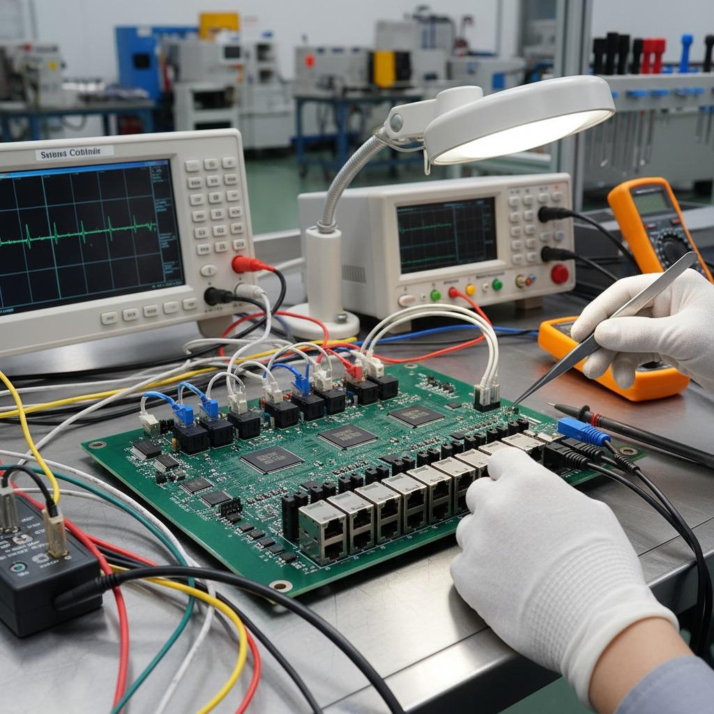
Here is where a capable manufacturing partner matters. hcdpcba offers SMT assembly, PCB prototyping, component sourcing, testing, and DFMA support. For a remote ceiling fan PCB or a more complex control board, that combination can reduce the usual friction between design intent and build reality. The value is not only in placing parts but in checking whether the design is practical to assemble and verify at scale.
Common mistakes in fan PCB sourcing
One common mistake is treating the controller as a generic PCB and only finalizing motor details late in the program. That usually forces redesigns. Another is ignoring service conditions. Ceiling fans run for long periods, often in warm ceilings, so margin matters. A third is assuming all suppliers can handle both the electronics and the manufacturing discipline needed for repeatable builds. They cannot.
Buyers should also be cautious about over-specifying features that add complexity without improving the user experience. A cleaner board with fewer failure points is often the better commercial choice, especially for high-volume consumer products.
What to ask before placing a build order
Before you release a BLDC ceiling fan PCB for production, ask the supplier how they handle BOM sourcing, incoming material checks, process control, and final test. If the board will ship with remote control functions, confirm how those functions are validated. If the design is still changing, ask for DFMA feedback early rather than after the first failed prototype.
It is also worth confirming whether the assembler can support both prototypes and production. hcdpcba states that it supports fast PCB prototyping, small and large SMT runs, OEM and ODM service, and one-to-one confidentiality measures. For teams managing new product development, that kind of continuity can save time, though the actual fit still depends on the project details.
Practical buyer advice
If you are comparing suppliers, do not stop at capability claims. Review the board structure, assembly method, and test strategy together. A good BLDC fan driver PCB is as much about stable manufacturing as it is about circuit design. Ask for realistic feedback on cost drivers, assembly risk, and any parts that may be difficult to source consistently. That conversation usually reveals more than a polished quotation.
For teams working on ceiling fans with remote control or smart-home integration, it helps to involve manufacturing early. A supplier that understands SMT processing, PCB assembly, and test planning is better positioned to flag hidden issues before they become field failures.
Next step for engineering and sourcing teams
If your project is at the prototype, redesign, or production-transfer stage, start by defining the motor requirements, control functions, and board assembly constraints. From there, a manufacturing partner like hcdpcba can help with PCB prototyping, SMT assembly, component sourcing, and test support. For teams that need a practical discussion rather than a generic quote, the most useful next step is a design review grounded in the actual board files and system requirements.