Why Power Supply PCBA Requires More Than Standard PCB Assembly
A power supply PCBA is one of the most critical electronic assemblies inside modern products because it directly controls energy conversion, voltage regulation, current delivery, protection, and system stability.
Unlike many control boards that mainly process signals, a power supply PCBA handles electrical energy. A small design mistake in component selection, PCB layout, thermal management, protection circuitry, or manufacturing control can cause problems throughout the entire product.
Common failures related to poor power supply PCBA design include:
- Unstable output voltage
- Excessive heat generation
- Component overheating
- Electrical noise affecting other circuits
- Unexpected shutdown
- Reduced product lifetime
- Safety risks
- EMC compliance issues
- Field failures after installation
For OEM buyers, sourcing a power supply PCBA is therefore not simply about finding a factory that can place components on a PCB.
The real question is:
Can the supplier manufacture a power electronics assembly that remains stable under the real operating conditions of the final product?
A reliable power supply PCBA requires coordination between:
- Circuit design
- Power component selection
- PCB material and layout
- Thermal design
- EMI control
- Component sourcing
- SMT and through-hole assembly
- Inspection
- Electrical testing
- Reliability validation
- Production consistency
HCDPCBA supports PCB prototyping, SMT assembly, component sourcing, testing, DFMA review, and OEM/ODM manufacturing for customized electronic assemblies. Buyers can review the company's broader PCBA Manufacturing Services before preparing a power board project.
What Is a Power Supply PCBA?
A power supply PCBA is a printed circuit board assembly designed to convert, regulate, distribute, or manage electrical power inside an electronic product.
Depending on the application, it may perform different functions.
Typical power supply PCBA functions include:
- AC voltage conversion
- DC voltage regulation
- Battery charging
- Power distribution
- Voltage protection
- Current protection
- Energy management
- Power monitoring
- Standby power control
Examples include:
- Industrial equipment power boards
- Projector power supply boards
- Smart home device power modules
- Automotive electronics power boards
- Medical equipment power assemblies
- Consumer electronics power controllers
- IoT device power management boards
- Charging system control boards
A power supply PCBA usually contains components with higher electrical and thermal requirements compared with standard control boards.
Typical components may include:
- MOSFETs
- Diodes
- Transformers
- Inductors
- Capacitors
- Power ICs
- Rectifiers
- Voltage regulators
- Current sensors
- Protection devices
- Connectors
- Heat dissipation structures
The exact architecture depends on input voltage, output requirements, efficiency target, operating environment, and safety requirements.
Main Types of Power Supply PCBA
Before selecting a manufacturing partner, buyers should define what type of power supply PCBA they need.
Different architectures create different manufacturing requirements.
AC/DC Power Supply PCBA
AC/DC power supply PCB assemblies convert alternating current from the mains supply into regulated direct current.
Common applications include:
- Consumer electronics
- Industrial equipment
- Lighting systems
- Smart appliances
- Projectors
- Control systems
Typical stages include:
- Input protection
- Rectification
- Power conversion
- Voltage regulation
- Filtering
- Output protection
Important design considerations include:
- Isolation requirements
- Transformer selection
- Safety distance
- Surge protection
- EMI filtering
- Thermal performance
- Efficiency
Because AC/DC boards connect directly to mains voltage, manufacturing requirements are generally more demanding than low-voltage DC boards.
DC/DC Converter PCBA
DC/DC power boards convert one DC voltage level into another.
Applications include:
- Battery-powered products
- Embedded systems
- Automotive electronics
- Industrial controllers
- Portable devices
Common converter types include:
- Buck converter
- Boost converter
- Buck-boost converter
- Multi-output converter
Important parameters include:
- Input voltage range
- Output voltage
- Output current
- Efficiency
- Ripple voltage
- Switching frequency
- Thermal performance
A DC/DC converter may occupy a small PCB area but still require careful layout because switching noise can affect sensitive circuits.
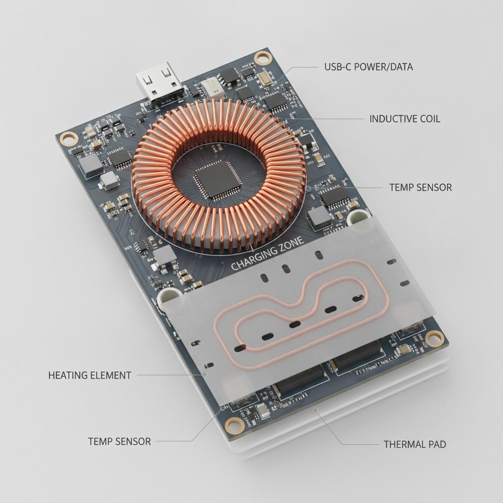
Battery Charging Power PCBA
Battery charging boards manage energy transfer between the power source and battery system.
They may include:
- Charging IC
- Protection circuit
- Battery monitoring
- Current sensing
- Temperature monitoring
- Communication interface
Applications include:
- Portable electronics
- Energy storage devices
- Smart equipment
- Battery-powered industrial products
Important considerations include:
- Charging algorithm
- Battery chemistry
- Thermal limits
- Over-current protection
- Over-voltage protection
- Short-circuit protection
Power Distribution PCBA
Some products require a power distribution board rather than a conversion board.
These assemblies manage:
- Multiple voltage outputs
- Power switching
- Load control
- Protection
- Monitoring
Applications include:
- Industrial systems
- Automation equipment
- Robotics
- Embedded platforms
The supplier must understand not only PCB assembly but also electrical testing requirements.
Key Components in Power Supply PCBA Manufacturing
Component selection directly influences power supply reliability.
A professional manufacturing process begins with understanding each component's electrical role.
Power Semiconductor Components
Power semiconductors are among the most critical components.
Examples include:
- MOSFETs
- IGBTs
- Diodes
- Rectifiers
- Power ICs
They determine:
- Switching performance
- Efficiency
- Heat generation
- Voltage tolerance
- Current capability
A component that appears suitable based only on voltage rating may still fail because of:
- Switching losses
- Thermal resistance
- Package limitations
- Frequency requirements
- Avalanche characteristics
Transformers and Inductors
Magnetic components are essential in many power supply designs.
They influence:
- Energy transfer
- Efficiency
- Noise
- Heat
- Size
Important factors include:
- Core material
- Winding design
- Insulation
- Temperature rise
- Leakage inductance
- Mechanical mounting
For production, magnetic components also create supply-chain considerations because custom transformers and inductors may require longer preparation cycles.
Capacitors
Capacitors affect:
- Filtering
- Ripple reduction
- Stability
- Energy storage
- Transient response
Important considerations include:
- Voltage rating
- Temperature rating
- Lifetime
- ESR
- Ripple current capability
Using a lower-cost capacitor with insufficient lifetime or ripple capability can reduce product reliability.
Connectors and Terminals
Power supply PCBAs often use connectors carrying significant current.
Selection should consider:
- Current rating
- Contact resistance
- Mechanical strength
- Temperature rise
- Insertion cycles
- Housing compatibility
Connector failure can interrupt the entire product even when the PCB circuit is correctly designed.
Protection Components
Protection circuits help prevent damage caused by abnormal conditions.
Common protection devices include:
- Fuses
- TVS diodes
- Surge protectors
- Current sensors
- Thermal protection devices
Protection design should match the final application environment.
Power Supply PCBA Design Factors OEM Buyers Should Review
A successful power board requires more than selecting suitable components.
The entire system needs to be considered.
Voltage and Current Requirements
The first design question is:
How much power does the final product actually need?
Define:
- Input voltage range
- Output voltage
- Maximum current
- Peak current
- Standby power
- Startup current
- Transient load
- Efficiency target
Many field failures happen because the design was tested only under normal conditions rather than worst-case operating conditions.
A power supply PCBA should be evaluated during:
- Startup
- Maximum load
- Sudden load changes
- Continuous operation
- Temperature extremes
PCB Layout for Power Electronics
Power PCB layout differs significantly from standard digital PCB layout.
Important areas include:
- High-current paths
- Switching loops
- Ground strategy
- Heat paths
- Sensitive signal separation
- Component placement
Poor layout may cause:
- Voltage instability
- Excessive EMI
- Component heating
- Reduced efficiency
- Unexpected noise coupling
High-Current Path Design
High-current traces should be designed according to:
- Current level
- Copper thickness
- Trace width
- Temperature rise
- Layer structure
- Via capacity
A narrow trace may work during a short test but fail during continuous operation.
Switching Loop Control
Switching converters create high-frequency current loops.
The layout should minimize:
- Loop area
- Parasitic inductance
- Noise radiation
- Coupling into sensitive circuits
Power switching components should be placed according to the electrical path rather than only mechanical convenience.
Ground Design
Grounding is one of the most important aspects of power supply PCBA design.
The designer should consider:
- Power ground
- Signal ground
- Analog ground
- Chassis ground
- Protection ground
Incorrect grounding can create:
- Noise problems
- Measurement errors
- Communication issues
- EMI failures
- Unstable control loops
- Unexpected reset behavior
The grounding strategy should be defined according to the converter topology, control IC requirements, sensing architecture, enclosure, and system interface.
In switching power supplies, high-current return paths should be kept short and controlled. Sensitive feedback and measurement circuits should not share uncontrolled current paths with noisy switching loops.
Thermal Management in Power Supply PCBA
Thermal design is one of the most important differences between power electronics and many standard digital PCB assemblies.
Every component that carries or switches current generates heat.
Important heat sources may include:
- MOSFETs
- Rectifiers
- Transformers
- Inductors
- Linear regulators
- Power resistors
- Bridge rectifiers
- High-current connectors
- Charging ICs
A power supply PCBA may operate correctly at room temperature during a short prototype test but fail after several hours inside a closed product.
Why Temperature Matters
Excessive temperature can reduce:
- Semiconductor reliability
- Capacitor lifetime
- Connector performance
- Transformer insulation life
- Solder joint reliability
- Overall product lifetime
Temperature also affects electrical parameters.
For example:
- MOSFET on-resistance can increase.
- Capacitor ESR can change.
- Regulator efficiency may decrease.
- Thermal protection may activate.
- Current capability may be reduced.
This means thermal validation should not be treated as an optional final check.
Component Placement for Heat Control
Heat-generating components should be placed with enough space for:
- Copper heat spreading
- Air circulation
- Thermal vias
- Heat sinks
- Mechanical clearance
Sensitive components should be kept away from major heat sources where practical.
For example, temperature-sensitive capacitors should not be positioned unnecessarily close to hot MOSFETs or transformers.
PCB Copper as a Heat Path
PCB copper can help distribute heat.
Design methods may include:
- Larger copper areas
- Thermal vias
- Multiple copper layers
- Thicker copper
- Heat-spreading planes
However, adding copper can also affect:
- Soldering behavior
- Thermal balance
- PCB cost
- Manufacturing difficulty
The design should balance thermal performance and manufacturability.
Heat Sink and Enclosure Integration
Some power supply PCBAs require:
- Aluminum heat sinks
- Thermal pads
- Thermal adhesive
- Metal enclosures
- Chassis contact
These mechanical elements should be considered during PCB development rather than added after overheating appears.
The assembly supplier should receive clear drawings and instructions if heat sinks, thermal pads, screws, clips, or insulating materials are part of the production scope.
EMI and EMC Risks in Power Supply PCBA
Switching power supplies are common sources of electromagnetic noise.
This noise can affect:
- Wireless modules
- Sensors
- Audio circuits
- Display systems
- Communication interfaces
- Camera electronics
- Microcontrollers
EMI problems can also prevent the final product from meeting its required regulatory performance.
Common EMI Sources
Typical sources include:
- MOSFET switching edges
- Transformer leakage
- High-frequency current loops
- Rectifier recovery
- Switching nodes
- Long high-current traces
Input EMI Filtering
An input filter may include components such as:
- Common-mode chokes
- X capacitors
- Y capacitors
- Differential-mode inductors
- Ferrite components
The exact filter depends on the power architecture and regulatory requirements.
For mains-powered products, component safety class and insulation requirements must also be considered.
PCB Layout for EMI Reduction
Important practices include:
- Minimize switching-loop area
- Keep noisy nodes away from sensitive circuits
- Maintain continuous return paths
- Control transformer placement
- Reduce unnecessary trace length
- Separate input and output sections where required
EMI control is easier when considered during schematic and PCB design rather than after the prototype fails a compliance test.
Creepage, Clearance, and Isolation Must Be Defined Early
For power supply PCBAs that handle higher voltages or mains input, electrical spacing becomes a critical safety requirement.
Two important concepts are:
Clearance — the shortest distance through air between conductive parts.
Creepage — the shortest path along the surface of an insulating material.
Required spacing depends on factors such as:
- Working voltage
- Pollution degree
- Material group
- Insulation type
- Overvoltage category
- Applicable product standard
The buyer should not simply tell the PCBA supplier:
“Please keep enough distance.”
The required safety criteria should be defined by the product design and applicable standard.
Primary and Secondary Isolation
In an isolated power supply, the design may include:
- Primary-side high-voltage circuitry
- Isolation transformer
- Secondary low-voltage circuitry
- Feedback isolation
- Isolation slots
The PCB layout needs to maintain the required separation between these areas.
Poor component placement or routing can reduce the effective creepage or clearance distance even when the schematic is electrically correct.
Power Supply PCB Material Selection
FR-4 is common in many power supply PCBAs, but the correct board specification should depend on electrical, thermal, and mechanical requirements.
Important parameters include:
- Board thickness
- Copper thickness
- Tg
- Layer count
- Surface finish
- Thermal performance
- Flame rating where applicable
Copper Thickness
Higher-current designs may require increased copper weight.
Typical options can include:
- 1 oz copper
- 2 oz copper
- Higher copper weights for specialized power boards
Higher copper can improve current handling and heat spreading, but it may affect:
- Etching tolerance
- Fine trace capability
- PCB cost
- Via design
- Soldering
The copper specification should match the actual current and thermal requirement rather than being selected only because “thicker is better.”
Mixed SMT and THT Assembly in Power Supply PCBA
Many power boards are mixed-technology assemblies.
SMT components may include:
- Control ICs
- MOSFET drivers
- Small resistors
- Ceramic capacitors
- Communication components
Through-hole components may include:
- Transformers
- Large electrolytic capacitors
- Relays
- Terminal blocks
- Connectors
- Inductors
- Fuse holders
This combination creates a more complex production sequence.
For buyers evaluating this type of board, HCDPCBA's Mixed Technology PCBA Guide explains how SMT and THT processes should be coordinated.
SMT Assembly
The SMT stage may involve:
- Solder paste printing
- Pick-and-place
- Reflow soldering
- AOI inspection
Power boards may contain large thermal pads or power packages that require careful solder paste design and reflow control.
Through-Hole Insertion
Large components may be installed manually or automatically depending on production volume and component type.
Important concerns include:
- Component orientation
- Lead preparation
- Mechanical fit
- Height control
- Seating
- Polarity
Wave or Selective Soldering
Through-hole joints may be processed using:
- Wave soldering
- Selective soldering
- Manual soldering
The correct process depends on:
- Board layout
- Component distribution
- Volume
- Thermal sensitivity
- Accessibility
The soldering method should be defined before mass production because it can influence PCB layout and component spacing.
Power Component Sourcing and BOM Control
Power electronics are particularly sensitive to component substitutions.
A replacement component with the same basic voltage or current rating may still behave differently.
Important parameters may include:
MOSFETs
- RDS(on)
- Gate charge
- Threshold voltage
- Switching speed
- Thermal resistance
- Package
- Avalanche capability
Diodes
- Forward voltage
- Reverse recovery
- Current rating
- Junction temperature
- Package
Capacitors
- Capacitance
- Voltage
- ESR
- Ripple-current capability
- Temperature rating
- Lifetime
Magnetics
- Inductance
- Saturation current
- Core material
- Winding resistance
- Insulation
- Thermal performance
Replacing one of these components without engineering review can affect:
- Efficiency
- Heat
- EMI
- Stability
- Lifetime
- Safety
For repeat production, the BOM should control:
- Manufacturer
- Exact part number
- Approved alternatives
- Revision history
- Supply status
A turnkey supplier can manage sourcing, but engineering approval should remain clearly defined. Buyers considering consolidated sourcing and manufacturing can review the Turnkey PCBA Manufacturing Guide.
DFMA for Power Supply PCBA
Design for Manufacturing and Assembly is especially important for power boards because electrical design, thermal behavior, and physical assembly interact closely.
Component Spacing
Large components can create:
- Soldering access problems
- Heat concentration
- Mechanical interference
- Inspection limitations
- Test-fixture difficulties
Heavy Component Support
Transformers, large inductors, and capacitors may require additional mechanical support.
Depending on the product, support may include:
- Adhesive
- Brackets
- Screws
- Clips
- Reinforcement
The objective is to reduce mechanical stress on solder joints during:
- Transportation
- Vibration
- Shock
- Product installation
Test-Point Planning
Test points should allow access to:
- Input voltage
- Output rails
- Feedback nodes
- Control signals
- Protection signals
- Ground reference
Testability should be considered during layout rather than after the production fixture is designed.
Inspection for Power Supply PCBA
Inspection should match the failure risks of the board.
SPI
Solder paste inspection can help identify:
- Insufficient paste
- Excess paste
- Misalignment
This is especially useful for power packages where solder coverage affects thermal performance.
AOI
AOI can help detect:
- Missing components
- Incorrect orientation
- Placement errors
- Visible soldering defects
X-Ray
X-Ray can be useful for components with hidden solder joints, such as:
- QFN
- BGA
- Power packages with exposed pads
X-Ray does not replace functional testing.
THT Inspection
Through-hole joints should be checked for:
- Solder fill
- Bridging
- Insufficient solder
- Component seating
- Polarity
- Mechanical alignment
Electrical Testing for Power Supply PCBA
A professional testing plan should move beyond simple continuity checks.
Input Current Test
Input current can indicate:
- Short circuits
- Incorrect component values
- Abnormal switching behavior
Output Voltage Test
Verify:
- Nominal voltage
- Regulation
- Tolerance
Multiple output rails should be checked individually.
Load Test
A power supply should be tested under realistic electrical load.
The test may include:
- No load
- Light load
- Nominal load
- Maximum load
The board should remain stable across the required range.
Load Regulation
Output voltage should remain within the defined limit when load changes.
Poor load regulation may indicate problems in:
- Feedback design
- Control loop
- Component tolerance
- PCB layout
Line Regulation
For products with a wide input range, the supply should be tested at:
- Minimum input
- Nominal input
- Maximum input
Ripple and Noise
Output ripple should be measured under defined conditions.
Excessive ripple may affect:
- Digital circuits
- Sensors
- Audio
- Communication
- Camera modules
Measurement method matters.
Probe grounding and bandwidth settings can significantly change the measured result.
Efficiency Test
Efficiency can be measured as:
Output Power / Input Power × 100%
Efficiency should be tested at several load conditions rather than only at one operating point.
Protection Tests
Depending on the design, testing may include:
- Over-current protection
- Over-voltage protection
- Short-circuit protection
- Thermal protection
- Reverse polarity protection
These tests should be defined by the engineering specification.
High-Voltage and Isolation Testing
For isolated or mains-connected power boards, additional tests may be required.
Possible tests include:
- Hi-pot / dielectric withstand
- Insulation resistance
- Ground continuity
The required test voltage, duration, leakage limit, and acceptance criteria should come from the applicable product safety requirements.
A PCBA supplier should not invent these values.
The buyer or product engineering team should specify them in the production documentation.
Functional Testing Should Match the Final Product
A board can pass voltage testing and still fail inside the final system.
Functional testing may need to verify:
- Power-up sequence
- Enable signals
- Communication interfaces
- Standby mode
- Fan control
- Charging behavior
- Protection response
- Interaction with the main control board
For some projects, the best functional test uses:
- Final-product fixture
- Simulated load
- Golden sample
- Automated test software
The test should replicate the most important operating conditions of the final product.
Burn-In and Reliability Validation
Some power supply projects require extended operation before release.
Burn-in testing can help reveal:
- Thermal problems
- Weak solder joints
- Component defects
- Unstable regulators
- Early-life failures
Burn-in may involve:
- Controlled load
- Elevated temperature
- Continuous operation
However, burn-in should be defined by actual project risk and product requirements.
It should not be added automatically to every project because it increases:
- Production time
- Electricity usage
- Fixture requirements
- Cost
Common Power Supply PCBA Failure Symptoms
| Failure Symptom | Possible Causes |
|---|---|
| No output | Fuse, MOSFET, control IC, transformer, soldering issue |
| Low output voltage | Overload, feedback error, wrong component |
| Output oscillation | Control-loop instability, layout, capacitor issue |
| Excessive heat | Low efficiency, undersized component, poor heat path |
| High ripple | Capacitor, layout, switching or filter problem |
| Random shutdown | Protection trigger, overheating, voltage drop |
| EMI test failure | Switching loop, filter, grounding, layout |
| Connector overheating | Current rating, contact resistance, soldering |
| Failure after hours | Thermal stress, capacitor or semiconductor issue |
| Batch inconsistency | Component substitution, process variation, test gap |
The correct diagnosis should combine:
- Electrical measurement
- Thermal measurement
- Visual inspection
- Component verification
- Functional testing
rather than replacing parts randomly.
Prototype Validation Before Production
The prototype stage should confirm more than whether the output voltage appears correct.
Electrical Verification
Verify:
- Input range
- Output voltage
- Current capability
- Startup
- Efficiency
- Ripple
- Protection
Thermal Verification
Measure temperature of critical components under:
- Nominal load
- Maximum load
- Worst-case ambient condition
EMI Pre-Compliance
Pre-compliance testing can identify major EMI risks before formal certification.
Mechanical Verification
Confirm:
- Connector position
- Component height
- Heat sink fit
- Board mounting
- Enclosure clearance
Pilot Production
A pilot batch helps determine whether the design can be manufactured repeatedly.
Review:
- First-pass yield
- Solder defects
- Manual assembly operations
- Component orientation
- Test time
- Rework
- Fixture performance
- Heat sink assembly
- Adhesive process
The pilot build should use production-intent materials where possible.
Production Release
Before mass production, the buyer should freeze:
- PCB revision
- Gerber files
- BOM
- Approved alternatives
- Assembly drawings
- Test specification
- Firmware if applicable
- Mechanical parts
- Heat sinks
- Labels
- Packaging
This configuration should become the reference for future repeat orders.
Power Supply PCBA Cost Drivers
The unit price depends on more than PCB size.
Major cost drivers include:
- PCB layer count
- Copper thickness
- Board material
- Power components
- Transformers
- Inductors
- High-value capacitors
- Through-hole labor
- Selective soldering
- Heat sinks
- Mechanical assembly
- Testing
- Burn-in
- Fixtures
- Order quantity
Why the Lowest Quote Can Be Misleading
Supplier A may quote only:
- PCB
- Components
- SMT
Supplier B may include:
- PCB
- Component sourcing
- SMT
- THT assembly
- Heat sink installation
- Functional testing
- Load testing
These quotations cannot be compared only by unit price.
Buyers evaluating broader manufacturing responsibility can also review HCDPCBA's Reliable PCBA Supplier Selection Guide.
How to Evaluate a Power Supply PCBA Manufacturer
Ask project-specific questions rather than generic questions such as “Can you make power boards?”
Engineering Review
Ask whether the supplier can review:
- Layout manufacturability
- Component spacing
- THT assembly
- Test access
- Thermal assembly
Material Control
Ask:
- How are key power components sourced?
- How are alternatives approved?
- How are transformers controlled?
Assembly Capability
Confirm:
- SMT
- THT
- Selective soldering
- Wave soldering
- Manual assembly
- Heat sink installation
Testing Capability
Confirm whether the project can support:
- Voltage test
- Current test
- Load test
- Ripple measurement
- Functional test
- Protection test
The exact test plan should still be defined by the buyer.
RFQ Checklist for Power Supply PCBA
A complete RFQ should include the following.
PCB Files
- Gerber
- Drill files
- Stack-up
- Copper weight
- Board thickness
BOM
Include:
- Manufacturer
- Part number
- Quantity
- Approved alternative
Electrical Requirements
Provide:
- Input voltage
- Output voltage
- Output current
- Maximum power
- Efficiency target
- Ripple limit
- Protection requirements
Assembly Requirements
Include:
- SMT
- THT
- Heat sink
- Adhesive
- Mechanical parts
- Coating if required
Testing Requirements
Define:
- Voltage
- Current
- Load
- Efficiency
- Ripple
- Functional test
- Protection test
- Burn-in if needed
Commercial Information
Include:
- Prototype quantity
- Pilot quantity
- Production forecast
- Packaging
- Delivery requirements
A detailed RFQ reduces quotation uncertainty and allows suppliers to evaluate the real production scope.
Frequently Asked Questions About Power Supply PCBA
What Is a Power Supply PCBA?
A power supply PCBA is an assembled PCB that converts, regulates, distributes, or controls electrical power inside an electronic product.
What Is the Difference Between a Power Supply PCB and Power Supply PCBA?
A power supply PCB is the bare printed circuit board.
A power supply PCBA includes the assembled components such as MOSFETs, capacitors, transformers, regulators, connectors, and control ICs.
What Components Are Commonly Used in Power Supply PCB Assembly?
Common components include:
- MOSFETs
- Diodes
- Transformers
- Inductors
- Capacitors
- Rectifiers
- Regulators
- Protection devices
Why Does a Power Supply PCBA Overheat?
Possible causes include:
- Low conversion efficiency
- Incorrect component selection
- Excessive current
- Poor PCB thermal design
- Inadequate heat sink
- High ambient temperature
Thermal measurement should be performed under realistic load conditions.
Why Is PCB Layout Important for a Power Supply?
Power circuits contain high-current and high-frequency switching paths.
Poor layout can increase:
- EMI
- Ripple
- Heat
- Switching losses
- Control instability
What Testing Is Needed for Power Supply PCBA?
Typical testing may include:
- Voltage
- Current
- Load
- Ripple
- Efficiency
- Protection
- Functional operation
High-voltage products may require additional isolation and safety tests.
Can a Power Supply PCBA Use Both SMT and THT Components?
Yes.
Many power boards combine SMT control electronics with through-hole transformers, capacitors, relays, inductors, and connectors.
Can Components Be Substituted During Production?
Only after engineering evaluation and approval.
Power components that appear similar may have different thermal, switching, lifetime, or safety characteristics.
How Should Buyers Compare Power Supply PCBA Suppliers?
Compare:
- Engineering support
- Material sourcing
- SMT/THT capability
- Testing
- Thermal assembly
- Change control
- Prototype-to-production support
Do not compare unit price alone.
What Files Are Needed for a Power Supply PCBA Quote?
Provide:
- Gerber files
- BOM
- Pick-and-place data
- Assembly drawings
- Electrical requirements
- Testing requirements
- Quantities
Complete project information leads to a more accurate quotation.
Conclusion
A reliable power supply PCBA depends on coordinated control of power components, PCB layout, thermal performance, EMI, assembly quality, and electrical testing. OEM buyers should define input/output requirements, BOM, protection functions, load conditions, and test limits before production.
For project evaluation, send your Gerber files, BOM, power specifications, quantities, and testing requirements through the HCDPCBA Contact Us page.