LED driver failures are rarely immediate.
Most systems operate normally during initial testing, but after months of use, issues begin to appear—brightness inconsistency, flickering, or premature failure of driver components. In many cases, these problems are not caused by circuit design itself, but by how the board was laid out, assembled, and thermally managed.
Typical challenges seen in LED driver projects include:
-
Output current drift under continuous operation
-
Heat accumulation around MOSFETs and inductors
-
Reduced efficiency due to layout-induced losses
-
Inconsistent performance across production batches
A structured approach to PCBA for LED drivers addresses these risks early. By combining thermal-aware layout, current path optimization, and manufacturing control, driver boards can maintain stable performance over long operating cycles rather than just passing initial validation.
Why LED Driver PCBA Requires More Than Standard Power Assembly
Although LED drivers fall under power electronics, their operating characteristics introduce unique constraints. Unlike general power boards, LED drivers often run continuously, with minimal load variation, which makes thermal accumulation and efficiency loss more critical over time.
For example, even a small increase in resistance along a current path can lead to measurable heat buildup. Over extended operation, this can raise component temperatures by 10–15°C, accelerating aging.
A reliable PCBA for LED drivers must therefore account for:
-
Continuous current stability rather than transient load response
-
Thermal balance across compact layouts
-
Long-term efficiency rather than short-term output accuracy
Projects that integrate these considerations at the PCBA level typically achieve more stable lumen output and reduced maintenance cycles.
Material and Structural Design in LED Driver Boards
Material choice in LED driver PCBAs is often underestimated, yet it directly affects heat dissipation and long-term stability.
In practical applications:
-
Standard FR-4 is sufficient for low-power indoor lighting
-
High-Tg materials are preferred in enclosed fixtures where heat accumulation is significant
-
Copper thickness (commonly 1–2 oz, sometimes higher) is selected based on current load
In high-power LED drivers, increasing copper thickness alone is not enough. The distribution of copper and its connection to thermal paths determines whether heat spreads evenly or concentrates locally.
In optimized PCBA for LED drivers, thermal vias and copper balancing are often used together to reduce localized hotspots, leading to:
-
10–20% reduction in peak temperature
-
Improved consistency in long-term output performance
Layout Decisions That Directly Affect Driver Performance
LED driver layouts are particularly sensitive to current loop design and switching paths.
For instance, placing switching components too far apart increases loop area, which can:
-
Increase EMI
-
Reduce efficiency
-
Introduce instability in current regulation
Similarly, routing high-current traces without considering return paths can create uneven current distribution.
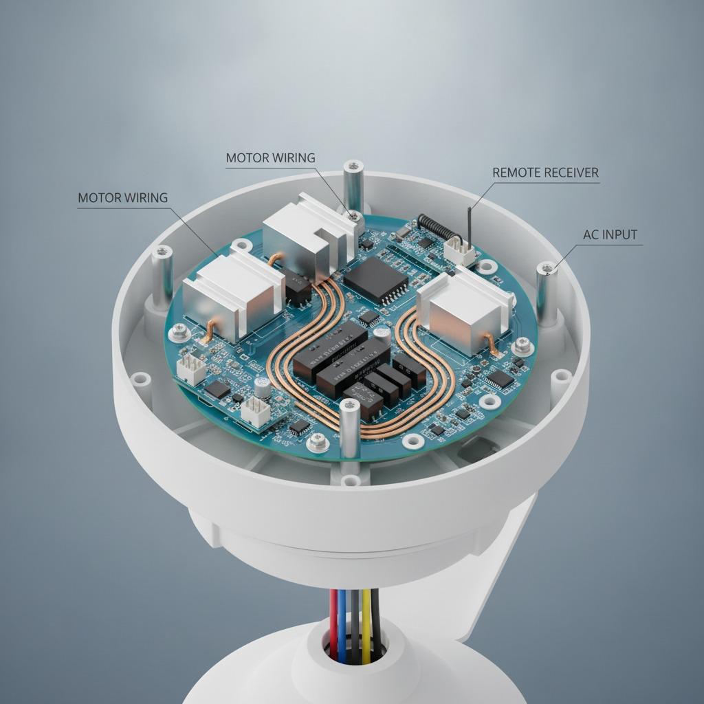
In well-executed PCBA for LED drivers, layout focuses on:
-
Minimizing loop area in switching circuits
-
Keeping current paths short and symmetrical
-
Separating control and power sections to reduce interference
These design practices often improve efficiency by 2–5%, which is significant in large-scale lighting deployments.
Environmental Considerations in LED Driver Applications
LED drivers operate in a wide range of environments—from indoor residential fixtures to outdoor industrial lighting systems.
Environmental factors influence PCBA design in several ways:
-
High ambient temperature requires enhanced thermal spreading
-
Humidity exposure necessitates coating-ready layouts
-
Enclosed housings limit airflow, increasing thermal stress
In outdoor or industrial applications, ignoring these factors can reduce product lifespan significantly.
Projects that incorporate environmental adaptation into PCBA for LED drivers typically show:
-
15–30% lower failure rates in field conditions
-
More stable performance across seasonal variations
Manufacturing and Inspection Strategy for LED Driver PCBA
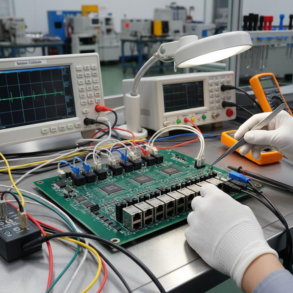
Manufacturing consistency plays a critical role in LED driver reliability. Small variations in solder volume or component placement can affect heat dissipation and electrical performance.
Key Manufacturing Factors and Their Impact
| Factor | Control Method | Typical Result |
|---|---|---|
| Solder consistency | Controlled stencil design | 20–30% fewer thermal defects |
| Component placement | Optimized placement accuracy | Improved heat distribution |
| Thermal design | Balanced copper layout | Reduced hotspot formation |
| Electrical testing | Output stability checks | Early defect detection |
| Batch monitoring | Process data tracking | Prevents performance drift |
These measures ensure that each production batch performs consistently under real operating conditions.
Compliance and Safety in LED Driver PCBA
LED driver boards must meet both electrical safety and electromagnetic compatibility standards.
Key considerations include:
-
Creepage and clearance distances for high-voltage sections
-
EMI control for CE/FCC compliance
-
Thermal limits aligned with long-term reliability requirements
A structured PCBA for LED drivers reduces certification risk by integrating these requirements into layout and manufacturing rather than addressing them later.
Frequently Asked Questions
Q1: Why do LED drivers fail after long-term use?
Heat accumulation and current instability gradually degrade components over time.
Q2: Can layout improve LED driver efficiency?
Yes. Optimized current paths and reduced loop area improve efficiency and reduce losses.
Q3: Is thermal design more important than component quality?
Both matter, but poor thermal design can negate the benefits of high-quality components.
Why LED Driver Performance Depends on PCBA Execution
A well-executed PCBA for LED drivers ensures that electrical design, thermal behavior, and manufacturing consistency work together. When these factors are aligned, LED systems maintain stable brightness, higher efficiency, and longer service life—even under continuous operation.
If you are evaluating whether your current design or supplier can support reliable LED driver production, reviewing layout strategy, thermal control, and manufacturing discipline is a practical starting point. You can explore our PCBA capabilities here:
👉 https://www.hcdpcba.com
For projects involving high-power lighting, outdoor systems, or long-duration operation, discussing your specific requirements early can significantly reduce lifecycle risk. You are welcome to contact our team here:
👉 https://www.hcdpcba.com/en/contact-us