How to Evaluate a Multi-port RJ45 CCU Controller Board
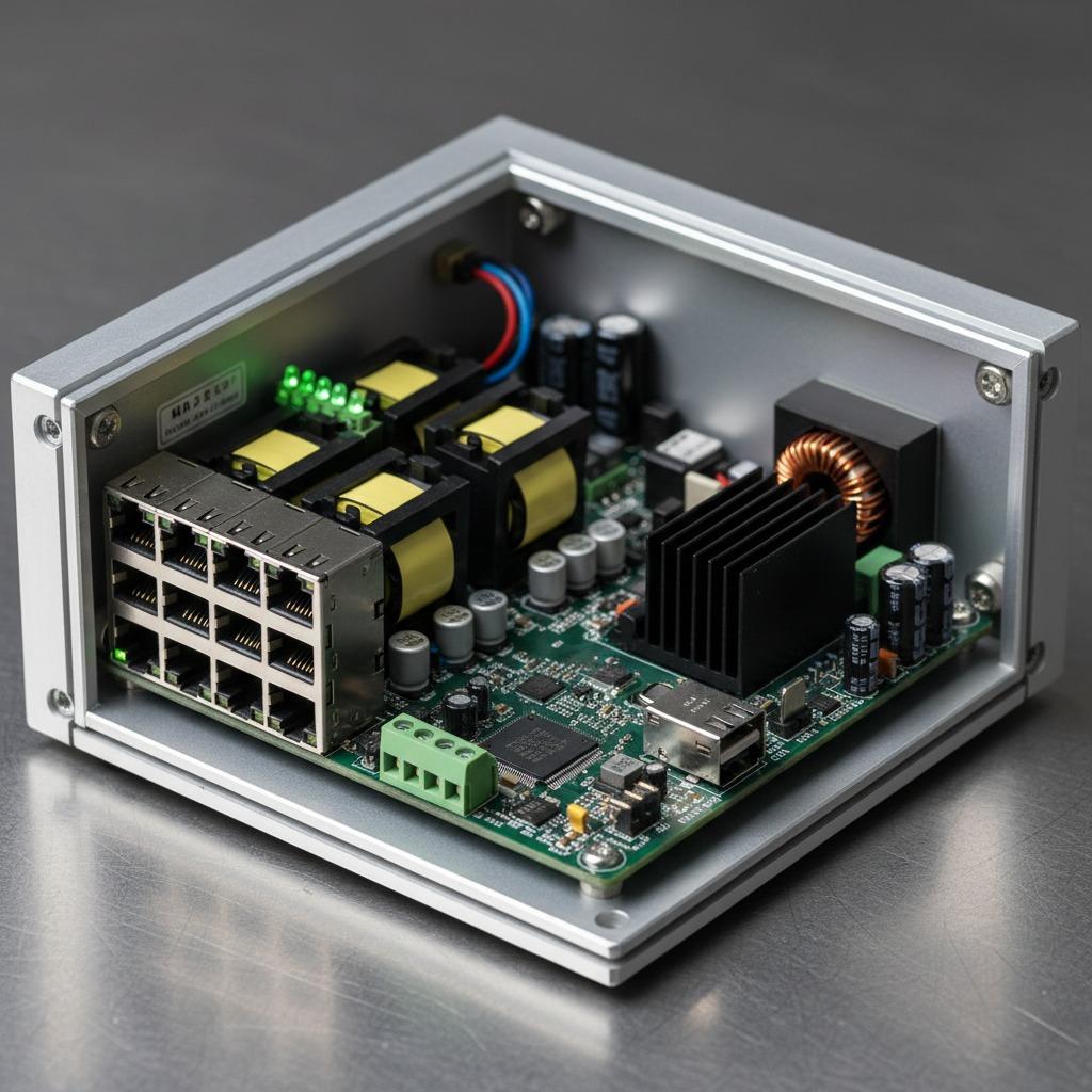
A Multi-port RJ45 CCU Controller Board is used when one central electronic assembly must manage several Ethernet-connected devices, sensors, controllers, or network segments. For engineers and sourcing managers, the decision is not simply about counting RJ45 connectors. The board must match the required communication architecture, power conditions, enclosure, software interface, production volume, and test strategy. This article explains the main design and purchasing considerations so teams can decide whether a standard board, a customized PCBA, or a complete OEM/ODM route is the better fit.
In industrial equipment, a central control board often sits between field devices and a higher-level monitoring or control system. If the network ports, processor, power conversion, isolation, and protection circuits are not specified together, problems can appear late in development: insufficient thermal margin, difficult cable routing, unstable communication, or a board that is awkward to manufacture.
Quick Reference: What Matters Most
- Port architecture: Confirm the number of RJ45 interfaces, their intended network topology, and whether ports must be electrically isolated.
- Processing and communication: Define the controller, Ethernet interface devices, operating environment, protocol requirements, and firmware ownership.
- Power design: Check input voltage, current demand, transient conditions, protection, and local regulation for processors and communication circuits.
- Mechanical integration: Review board dimensions, connector orientation, mounting holes, cable access, and enclosure clearances.
- Manufacturing readiness: Assess component sourcing, SMT capability, inspection, functional testing, and design-for-manufacturing feedback.
These points are connected. Adding ports may increase routing complexity, power consumption, connector crowding, and test time. A technically capable board can still be the wrong production choice if it cannot be assembled or serviced efficiently.
Understanding the Board’s Role in an Industrial System
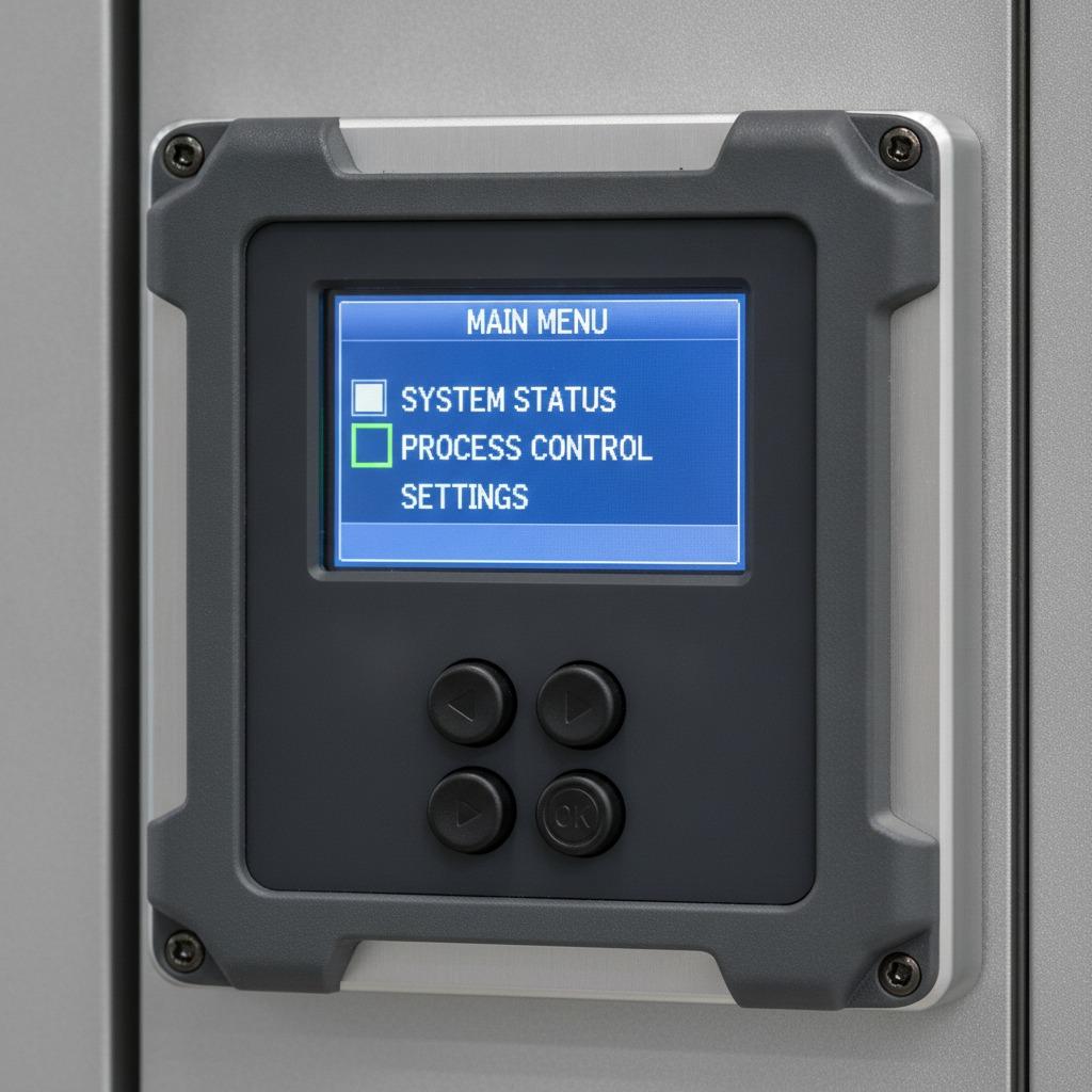
A multi-port controller board may act as a communications hub, a local gateway, or the main control unit for a piece of equipment. In a factory automation system, it could exchange data with drives, sensors, human-machine interfaces, or supervisory systems. In energy equipment, a related design may serve as a charging pile control board, coordinating communication, status monitoring, protection signals, and user-interface functions.
The word “central” should be treated carefully. A Central Control Unit Board is not automatically a complete system controller. Some projects require only Ethernet switching and protocol conversion, while others require real-time processing, storage, input/output control, watchdog functions, and secure remote management. The buyer should prepare a block diagram before asking a manufacturer for a quotation.
Key Design Areas
RJ45 Port Configuration
Start with the actual function of each port. Are the ports independent interfaces, switch-connected ports, uplinks, service ports, or a mixture? The answer affects the Ethernet devices, PCB routing, firmware, and test fixtures. Connector placement also deserves attention. Ports that are too close together may make cable insertion difficult, while a connector layout that ignores the enclosure can force a mechanical redesign.
Industrial installations may expose communication interfaces to electrical noise, long cables, or accidental connection events. Depending on the application, the design may need surge protection, filtering, magnetic isolation, shield management, and a considered chassis-ground strategy. These requirements should be settled during schematic and PCB review rather than added after the first prototype fails a system test.
Processing, Power, and Thermal Conditions
An Industrial CCU PCBA commonly combines a processor or microcontroller with Ethernet interface circuitry, memory, power regulation, status indicators, and application-specific inputs or outputs. The correct architecture depends on data throughput, response time, protocol stack, cybersecurity requirements, and whether the system must continue operating after a communication interruption.
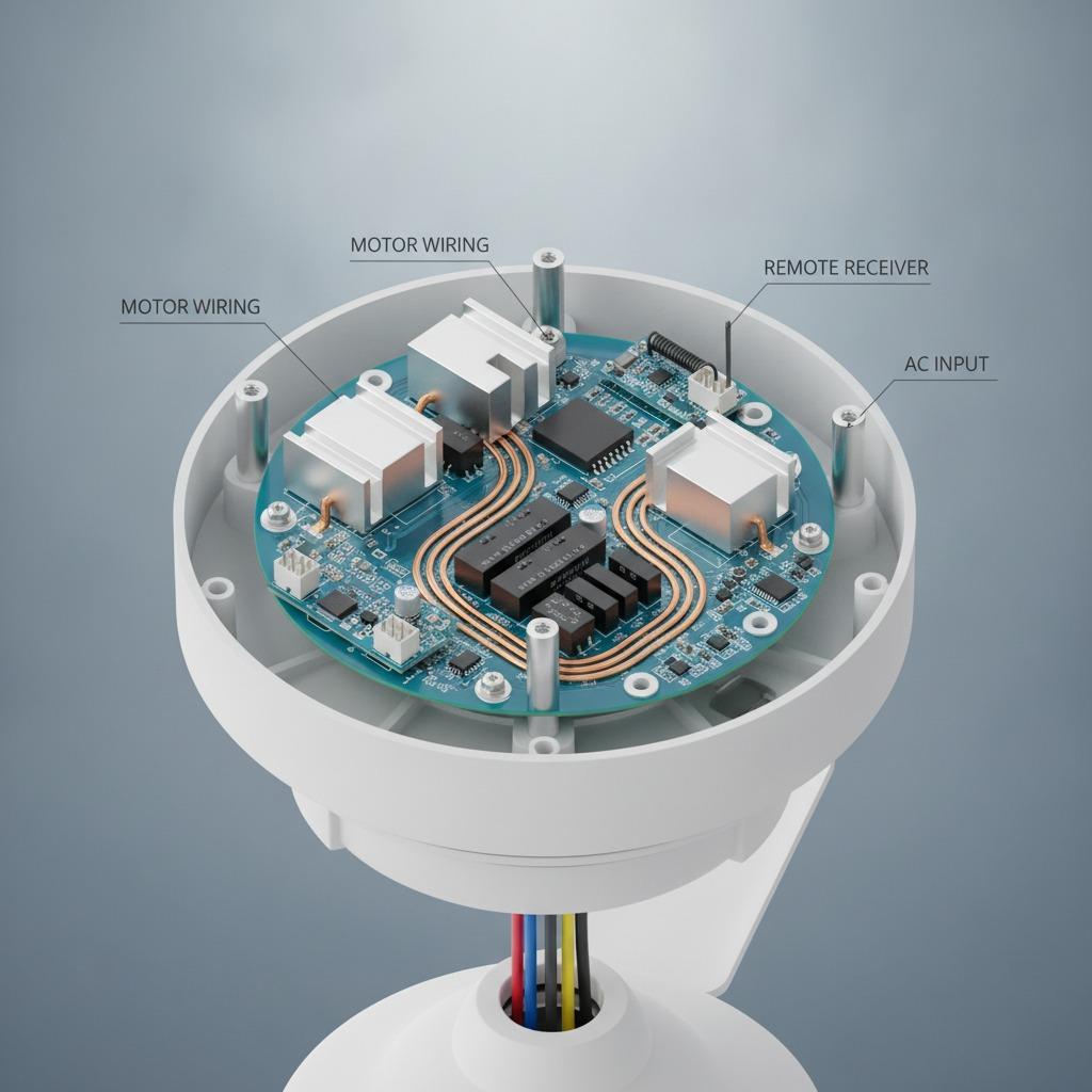
Power design is equally practical. Review the incoming supply range, reverse-polarity protection, overcurrent protection, transient suppression, and the heat produced by regulators and communication components. A board installed inside a sealed cabinet may have little airflow. Even when individual components remain within their stated limits, accumulated heat can reduce operating margin and complicate long-term reliability.
PCB Construction and Assembly
An Industrial Communication PCBA may require a multilayer PCB to provide controlled routing, signal integrity, ground continuity, and sufficient space for several interfaces. HCDPCBA states that it supplies customized multilayer, HDI, and high-frequency PCBA products for industrial control, medical, automotive electronics, communications, and other applications. The appropriate construction should be selected from the electrical and mechanical requirements, not from the layer count alone.
Assembly details also affect yield. Fine-pitch devices, board-to-board connectors, shielded components, and mixed through-hole and SMT parts may require a defined placement and inspection strategy. HCDPCBA provides SMT placement for both small and larger production runs, along with PCB prototyping, component sourcing, assembly, and testing. This combination can be useful when the project needs a direct path from engineering samples to repeat production.
What to Request From a Manufacturing Partner
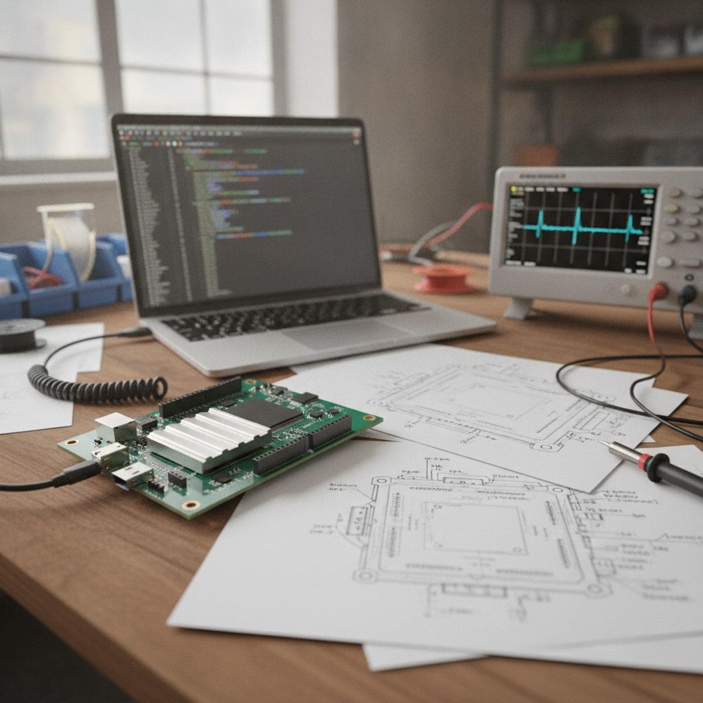
A useful RFQ package should include the schematic, preliminary or released PCB files, bill of materials, Gerber or ODB++ data where applicable, mechanical drawings, assembly drawings, test requirements, and expected production quantity. Also state which components are customer-specified and which may be substituted after approval.
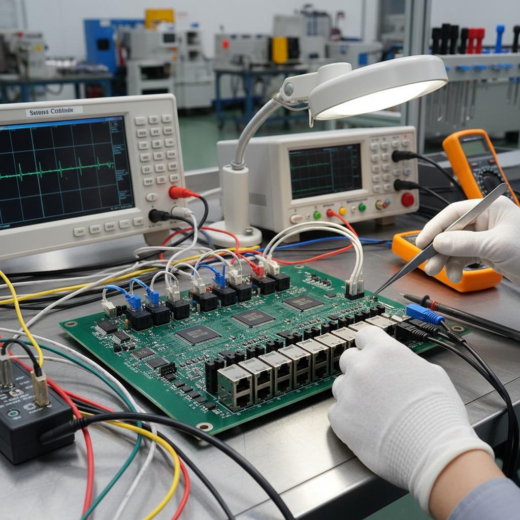
Ask how the supplier will handle component availability, obsolete parts, moisture-sensitive devices, programming, inspection, and functional testing. For a controller board, visual inspection alone is not enough. The test plan may need power-up checks, programming verification, port communication checks, input/output simulation, and a defined pass/fail record. Exact testing depends on the application and should be agreed before production.
DFMA review is particularly valuable before the layout is frozen. HCDPCBA offers design-for-manufacturing and design-for-assembly analysis intended to reduce production cost and improve efficiency. A review can identify crowded solder joints, unnecessary component variation, awkward test access, or connectors that are difficult to place consistently.
Common Purchasing Mistakes
- Specifying the number of ports without describing the network topology.
- Leaving isolation, shielding, and surge protection decisions until after the prototype.
- Approving a component list without checking lifecycle and supply risk.
- Ignoring programming and functional-test access during mechanical design.
- Comparing quotations only by board price rather than including tooling, test fixtures, engineering work, and approved substitutions.
One practical warning: a low-cost controller board can become expensive if every revision requires a new fixture, new firmware image, or manual rework. Ask for a clear revision-control process and identify who owns the manufacturing files and test documentation.
FAQ
Is a multi-port board suitable for every Ethernet application?
No. The required port count, switching arrangement, protocol behavior, bandwidth, isolation, and environmental conditions must be reviewed together. A simple network hub and a real-time industrial controller have very different design needs.
Should the board be designed as a custom PCBA?
Customization is usually justified when the equipment has specific port layouts, power inputs, protocols, I/O functions, or enclosure constraints. A standard solution may be faster for evaluation, but it may carry unused circuitry or create integration compromises.
Can HCDPCBA support more than SMT placement?
According to the supplied company information, HCDPCBA provides PCB prototyping, SMT placement, component sourcing, assembly, testing, DFMA, OEM, and ODM services. It also reports experience serving industrial control, communications, power, automotive electronics, medical, security, and IoT applications.
Next Step for Buyers
Before requesting a quote for a Multi-port RJ45 CCU Controller Board, prepare the port map, power requirements, protocol list, mechanical envelope, environmental assumptions, production quantity, and test expectations. HCDPCBA can be contacted at +86 18924624188 for discussion of customized PCBA, prototype, assembly, and testing requirements. A well-defined technical package will produce a more useful quotation and reduce avoidable redesign during production transfer.