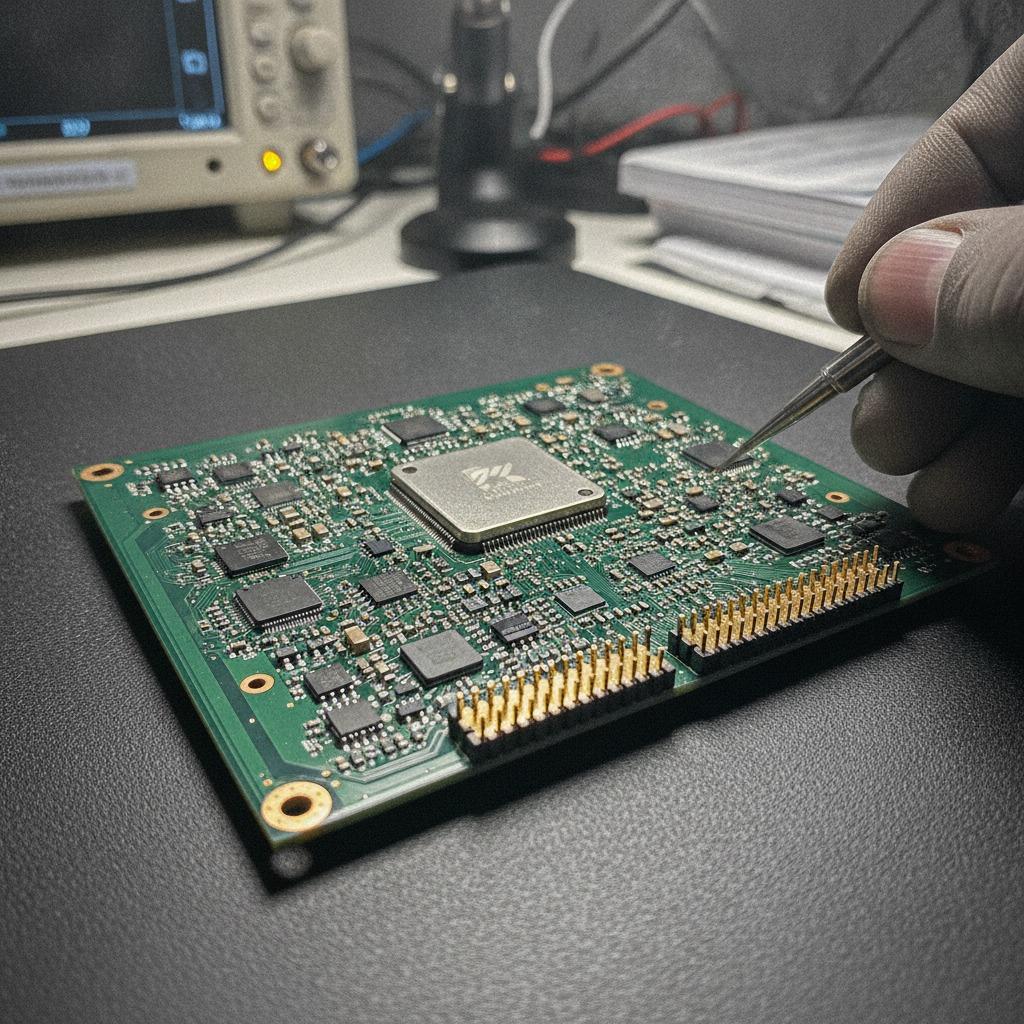
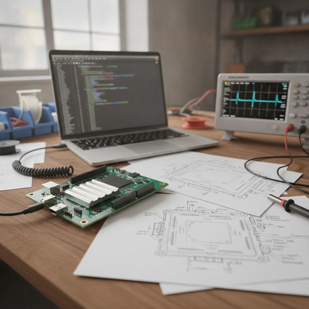
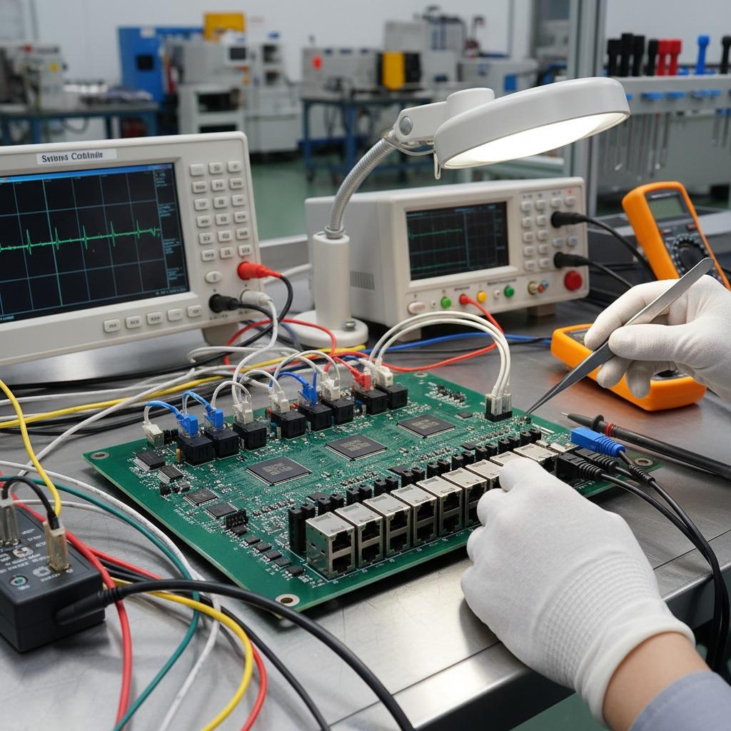
Why Camera Module PCBA Projects Fail After the First Prototype
A camera module PCBA is often judged too early. If the image sensor powers on and a host system displays video, the prototype may be considered successful. That result proves only that one hardware and software combination can produce an image under one test condition.
It does not prove that the same board will operate reliably after enclosure integration, temperature rise, cable movement, firmware updates, component substitutions, or production scale-up.
Camera electronics combine several sensitive domains on a small assembly:
- High-speed image data
- Low-noise analog and digital power
- Clock and reset timing
- Fine-pitch components
- FPC or board-to-board connectors
- Firmware and sensor initialization
- Optical alignment
- Thermal behavior
- Image-quality validation
A failure in any one of these areas can appear as no image, frame loss, visible bands, image noise, unstable color, USB disconnection, sensor reset, poor focus, or batch-to-batch variation.
This guide focuses on the engineering and production-validation layer of camera module PCB assembly. It does not repeat the general supplier-selection content already covered in the Camera Module PCB Assembly Supplier Guide.
Instead, it explains what OEM teams must define, test, document, and release before a camera module PCBA can become a stable production item.
Define the Product Boundary Before Requesting a Quote
The phrase “camera module” can describe several different deliverables. If the transaction object is not clear, suppliers may quote different scopes while appearing to quote the same project.
Camera Sensor Board
A sensor board usually contains the CMOS image sensor and the local circuits needed to support it.
Typical functions include:
- Sensor power filtering
- Reference clock
- Reset and standby control
- I²C or another control bus
- MIPI CSI-2, DVP, or another image output
- FPC or board-to-board connector
- ESD protection
- Local decoupling
- Test points
A sensor board may not include the lens, image signal processor, USB bridge, wireless connectivity, video compression, or final-product power architecture.
Camera Module PCBA
A camera module PCBA may include the sensor and additional electronics such as:
- USB bridge or interface controller
- Image signal processor
- EEPROM or flash memory
- MCU
- Power conversion
- IR-cut filter driver
- Infrared LED control
- Microphone or audio circuit
- Status indicators
- Local storage or configuration devices
The exact scope must be defined in the RFQ.
Camera Mainboard
A camera mainboard normally has a broader system role. It may contain:
- Application processor or SoC
- DDR memory
- eMMC or flash
- Ethernet
- Wi-Fi or Bluetooth
- Audio
- Video encoding
- Storage
- Multiple camera inputs
- AI inference
- Product-level I/O
An AI Camera PCBA is usually closer to this category than to a basic image sensor board.
Complete Camera Module or Finished Camera
A complete module may also include:
- Lens
- Lens holder
- Optical filter
- Sensor-to-lens alignment
- Housing or bracket
- Cable
- Focus adjustment
- Calibration
- Final image test
A finished camera adds the enclosure, host electronics, software, networking, power input, regulatory responsibilities, labeling, and packaging.
Responsibility Matrix
| Project Element | Buyer | PCBA Supplier | Optical/Module Supplier | Final Integrator |
|---|---|---|---|---|
| Sensor selection | Often | Support | Support | Input |
| Schematic and PCB design | Often | Review or design support | Input | Input |
| PCB fabrication | Usually | |||
| Component sourcing | Optional | Usually or shared | ||
| SMT assembly | Usually | |||
| Lens and sensor alignment | If included | Usually | ||
| Firmware and drivers | Often | Programming support | Sometimes | Often |
| ISP tuning | Often | Only if contracted | Sometimes | Often |
| Image validation | Shared | Manufacturing test | Optical test | System test |
| Final enclosure integration | Usually | |||
| Market certification | Product owner | Manufacturing evidence | Module evidence | Product owner |
The responsibility split should be written, not assumed. Buyers needing deeper information on optical integration can review the Lens and Sensor Assembly Factory Guide.
Translate Product Requirements Into Camera PCBA Specifications
The camera module PCBA should be developed from product-level requirements rather than from a generic sensor reference design.
Imaging Requirements
Define:
- Resolution
- Frame rate
- Pixel format
- Field of view
- Low-light requirement
- Dynamic range
- Color or monochrome output
- Infrared operation
- Rolling or global shutter
- Trigger or synchronization
- Maximum exposure time
- Image latency
- Acceptable frame loss
These requirements influence sensor selection, interface bandwidth, memory, processing, power, thermal design, and testing.
Mechanical Requirements
Define:
- Board dimensions
- Mounting-hole locations
- Sensor optical center
- Component-height limits
- Connector location
- Cable insertion direction
- Lens-holder interface
- Enclosure clearance
- Allowed board warpage
- Shock and vibration conditions
- Service or replacement requirements
A camera board can be electrically correct but unusable because the sensor center does not align with the lens opening or the FPC latch cannot be accessed after assembly.
Environmental Requirements
Specify:
- Operating temperature
- Storage temperature
- Humidity
- Condensation risk
- Dust exposure
- Indoor or outdoor use
- ESD exposure
- Vibration
- Continuous operating time
- Expected product lifetime
Environmental requirements should influence component grade, PCB material, connector choice, protective coating, thermal validation, and packaging.
Production Requirements
Define:
- Prototype quantity
- Pilot quantity
- Expected annual volume
- Product lifecycle
- Traceability depth
- Test-record requirements
- Repair policy
- Approved component alternatives
- Packaging
- Labeling
- Firmware-control method
A camera module intended for a short-lifecycle consumer product and one intended for a long-life industrial platform require different supply-chain and change-control strategies.
Select the Interface as a System Decision
Interface selection determines far more than the connector. It affects PCB stack-up, routing, firmware, host compatibility, cable architecture, test fixtures, and final-device validation.
MIPI CSI-2 Camera Module PCBA
MIPI CSI-2 is widely used for direct connection between an image sensor and an application processor, SoC, FPGA, or embedded computing platform.
Its advantages include:
- High data rate
- Small connector footprint
- Fewer signal lines than a parallel bus
- Direct integration with many embedded processors
- Suitability for compact products
Its risks include:
- Tight signal-integrity requirements
- Sensor and host compatibility
- Lane mapping
- Clock configuration
- Device-tree or driver dependency
- FPC channel quality
- Difficult debugging without the correct host platform
The engineering team should define:
- D-PHY or C-PHY
- Number of data lanes
- Lane rate
- Clock mode
- Lane mapping
- Connector pinout
- Differential impedance
- Maximum FPC length
- Host receiver capability
- Sensor initialization sequence
A MIPI board can pass continuity testing and still fail to stream because the electrical channel, lane configuration, sensor registers, or host software is incorrect.
USB Camera PCBA
A USB camera board usually adds a bridge, ISP, or controller between the image sensor and the host.
Advantages can include:
- Easier connection to PCs and terminals
- Standardized cable ecosystem
- Potential UVC compatibility
- Simplified host integration
- Longer practical cable options than direct sensor interfaces
Important design questions include:
- USB 2.0 or USB 3.x
- Required data rate
- Video compression or raw output
- UVC support
- Connector type
- Cable length
- Bus-powered or externally powered operation
- Enumeration behavior
- USB descriptors
- Operating-system compatibility
- Firmware-update method
A successful enumeration test does not prove that the board can stream the required resolution continuously without dropped frames or thermal instability.
DVP or Parallel Camera Interface
A parallel camera interface may be suitable for MCUs, selected processors, legacy products, or lower-bandwidth designs.
Key factors include:
- Pixel-clock frequency
- Data-bus width
- Horizontal and vertical synchronization
- Routing skew
- Connector pin count
- EMI
- Host input timing
- PCB space
Parallel interfaces can appear simpler at the protocol level but require more traces, connector pins, and routing area.
Ethernet or IP Camera Electronics
An Ethernet camera assembly normally includes more than a sensor interface.
It may contain:
- Video-processing SoC
- DDR
- Flash or eMMC
- Ethernet PHY
- Magnetics
- RJ45 connector
- PoE circuitry
- Audio
- Storage
- IR control
- Network firmware
This should be quoted as a camera mainboard or IP camera PCBA rather than a simple sensor board.
Camera Interface Comparison
| Interface | Best Fit | Main Advantage | Main Engineering Risk |
|---|---|---|---|
| MIPI CSI-2 | Embedded devices, robotics, edge systems | Compact high-speed connection | Signal integrity and host-driver integration |
| USB | PCs, kiosks, terminals, instruments | Easier host connectivity | Bridge firmware, bandwidth and cable behavior |
| DVP/Parallel | MCU and legacy platforms | Direct and sometimes simpler control | High pin count and routing skew |
| Ethernet/IP | Security and remote monitoring | Network-ready architecture | Larger hardware, firmware and compliance scope |
| Custom Bridge | Specialized equipment | Fits proprietary system | Higher validation and lifecycle burden |
The correct interface is the one that fits the complete product architecture, not merely the easiest option for the first prototype.
Design the Image Sensor and Supporting Circuits as One Subsystem
The image sensor cannot be isolated from the circuits that power, clock, configure, and connect it.
Sensor Selection
A sensor should be evaluated against:
- Optical format
- Resolution
- Pixel size
- Shutter type
- Dynamic range
- Low-light behavior
- Frame-rate modes
- Output interface
- Package
- Temperature range
- Driver support
- Lifecycle status
- Availability
- Lens ecosystem
Selecting a sensor only from a resolution number can create problems in power, optics, software, and supply.
Clock Design
The input clock may come from:
- Crystal oscillator
- MEMS oscillator
- Processor clock output
- Dedicated clock generator
The design should control:
- Frequency
- Accuracy
- Jitter
- Voltage level
- Startup time
- Routing
- Return path
- EMI
- Sensor mode compatibility
A clock that appears on an oscilloscope is not automatically within the sensor’s timing and signal-quality requirements.
Reset, Standby, and Power-Down Signals
These control signals should have defined default states.
Review:
- Pull-up or pull-down values
- Power-domain compatibility
- Host GPIO voltage
- Startup condition
- Reset pulse width
- Standby behavior
- Power-down sequence
- Recovery after brownout
Floating or incorrectly timed control signals can create intermittent startup failures that are difficult to reproduce.
Sensor Control Bus
I²C is commonly used for sensor configuration, but the implementation still needs review.
Important details include:
- Logic voltage
- Pull-up values
- Address selection
- Bus capacitance
- Level shifting
- Test access
- Multiple-device conflicts
- Clock stretching
- Firmware timeout
- Error recovery
The production test should verify sensor identification and selected register access rather than only checking bus continuity.
Engineer Power Integrity for Image Quality, Not Only Voltage
Camera sensors can convert power-supply problems into visible image defects.
Possible symptoms include:
- Horizontal bands
- Vertical bands
- Flicker
- Random image noise
- Color shift
- Unstable black level
- Frame loss
- Sensor reset
- Failure during mode switching
Identify Every Power Rail
A camera module may require separate rails for:
- Sensor analog
- Sensor digital core
- Sensor I/O
- ISP
- USB bridge
- Memory
- MCU
- IR-cut driver
- Infrared LEDs
- Audio
- Wireless devices
Each rail should have a defined voltage, tolerance, current, startup behavior, and noise target.
Measure Dynamic Load Conditions
Current should be evaluated during:
- Power-up
- Sensor initialization
- Standby
- Preview
- Full-resolution streaming
- Maximum frame rate
- Exposure changes
- IR-cut switching
- Infrared illumination
- Wireless transmission
- Firmware update
A regulator that is stable during idle operation may droop when the sensor and interface enter a high-bandwidth mode.
LDO and Switching-Regulator Trade-Off
An LDO may provide lower noise but can generate significant heat when voltage drop and current are high.
A switching regulator improves efficiency but introduces:
- Ripple
- Switching harmonics
- High-current loops
- Magnetics
- EMI
- Layout sensitivity
A common strategy is to use efficient switching conversion for the main rails and local low-noise regulation or filtering near sensitive circuits.
The correct architecture depends on input voltage, current, board size, enclosure temperature, image requirements, and cost.
Decoupling and Placement
Decoupling capacitors should be selected and placed according to the sensor and supporting IC requirements.
Consider:
- Capacitor value
- Package size
- DC-bias behavior
- Temperature characteristic
- Placement distance
- Via inductance
- Plane connection
- Bulk capacitance
- Rail isolation
Adding more capacitance without understanding the impedance path does not automatically solve power noise.
Power Sequencing
Document:
- Rail order
- Delay between rails
- Clock timing
- Reset timing
- Control-bus availability
- Shutdown sequence
- Standby sequence
- Brownout recovery
If firmware controls the sequence, firmware becomes part of the manufacturing configuration and must be version controlled.
Control High-Speed Signal Integrity Across PCB, Connector, and FPC
The high-speed channel includes more than the PCB traces.
It may include:
- Sensor package escape
- PCB differential pairs
- Vias
- Connector
- FPC
- Host connector
- Host PCB routing
- Receiver termination
Each transition contributes loss, discontinuity, and crosstalk.
PCB Stack-Up
The stack-up should provide:
- Controlled impedance
- Continuous reference planes
- Predictable dielectric thickness
- Suitable copper weight
- Adequate power distribution
- Manufacturable trace geometry
- Separation between sensitive and noisy circuits
A small board is not automatically suitable for a low layer count. Compact camera layouts can require multiple layers to maintain reference planes and route dense sensor, power, and control circuits.
Differential Pair Routing
For MIPI, USB, and similar interfaces, control:
- Pair width and spacing
- Differential impedance
- Intra-pair length relationship
- Reference-plane continuity
- Via count
- Stubs
- Coupling to switching nodes
- Connector transition
- Escape geometry
The design should follow the requirements of the actual sensor, bridge, host, PCB fabricator, and connector system.
Return-Path Continuity
High-speed currents need a continuous return path.
Risks include:
- Crossing plane splits
- Reference-plane voids
- Long transitions without ground vias
- Poorly placed ESD components
- Connector grounds separated from the reference plane
- Excessive routing near DC/DC switching loops
A trace can be geometrically matched and still perform poorly if its return path is interrupted.
FPC and Cable Definition
The RFQ and drawing package should specify:
- Connector part number
- Pitch
- Pin count
- Contact direction
- Latch style
- FPC thickness
- Cable length
- Layer construction
- Ground-pin distribution
- Shielding
- Bend radius
- Cable routing
- Retention method
FPCs should not be treated as generic accessories. A change in construction or length can alter the signal channel and mechanical reliability.
Plan EMI, ESD, and Grounding With the Product Enclosure
Camera electronics combine high-speed digital signals with sensitive image and audio circuits.
Common Noise Sources
Noise can come from:
- DC/DC converters
- Processor clocks
- USB
- MIPI
- DDR
- Ethernet
- Wi-Fi
- IR LED switching
- Motors
- Long cables
- External power adapters
Sensitive Victims
Sensitive circuits may include:
- Sensor analog rails
- Reference voltages
- Reset lines
- Control bus
- Microphone input
- Oscillator
- Exposure or trigger inputs
ESD Protection
External connectors may require suitable protection.
Selection should consider:
- Working voltage
- Clamping behavior
- Signal bandwidth
- Parasitic capacitance
- Surge requirement
- Package
- Placement
- Ground-return path
Protection should be located according to the intended transient path. A component placed far from the connector may allow ESD current to enter sensitive board areas before reaching the protection network.
Shield and Chassis Strategy
Define:
- Whether a shield can is required
- Shield connection points
- Chassis-ground relationship
- FPC shield termination
- Mounting-hole grounding
- Enclosure material
- Conductive gasket or coating
- Lens-holder electrical behavior
A shield should complement good PCB design, not compensate for uncontrolled routing or power noise.
Manage Thermal Behavior Before Image Quality Changes
A camera module often operates inside a compact enclosure with limited airflow.
Heat sources may include:
- Image sensor
- ISP
- USB bridge
- SoC or NPU
- DDR
- Regulators
- Infrared LEDs
- Wireless module
- Nearby product electronics
Temperature can influence:
- Dark current
- Hot pixels
- Random noise
- Color stability
- Oscillator behavior
- Regulator margin
- Component life
- Focus stability
Thermal Validation Conditions
Test the board under:
- Maximum resolution
- Maximum frame rate
- Long-duration streaming
- Infrared operation
- Wireless transmission
- Maximum ambient condition
- Final enclosure
- Intended cable arrangement
- Worst-case input voltage
An exposed-board test at room temperature is not equivalent to operation in a sealed housing.
Thermal Design Methods
Possible measures include:
- Copper spreading
- Ground planes
- Thermal vias
- Component separation
- Heat transfer to enclosure
- Thermal pads
- Controlled airflow
- Lower-loss regulators
- Duty-cycle control
- Firmware thermal management
Thermal solutions should not create optical or mechanical problems. For example, pressure from a thermal pad should not warp the board or disturb sensor-to-lens alignment.
Coordinate PCB Mechanics With Lens and Sensor Alignment
Image performance depends on geometry as well as electronics.
Sensor Optical Center
The PCB drawing should define the sensor’s optical center relative to:
- Board edges
- Mounting holes
- Lens-holder features
- Enclosure opening
- Reference datums
A small positional error can create assembly difficulty, vignetting, or inconsistent image alignment.
Board Flatness and Mechanical Stress
Board warpage or uneven fastening can change the relationship between the sensor and lens.
Potential causes include:
- Panel stress
- Depanelization
- Screw torque
- Connector force
- Enclosure interference
- Uneven thermal pads
- Unsupported board areas
Mechanical validation should therefore include the assembled product, not only the free PCB.
Lens Holder and Adhesive
If the module scope includes a lens holder or focus process, define:
- Holder material
- Mounting method
- Adhesive
- Cure process
- Focus procedure
- Locking method
- Cleanliness
- Allowed rework
- Traceability
Optical assembly needs different controls from standard SMT production.
Cleanliness
Dust, fibers, flux residue, fingerprints, solder particles, and adhesive contamination can affect image quality.
The process route should identify:
- When the sensor is exposed
- When cleaning occurs
- Whether conformal coating is used
- When the lens is installed
- How modules are protected between operations
- Packaging cleanliness
Apply DFMA to Camera Module PCB Assembly
A design can be electrically correct and still be difficult to manufacture consistently.
Fine-Pitch and Bottom-Terminated Packages
Camera boards may include:
- QFN
- BGA
- LGA
- CSP
- Fine-pitch FPC connectors
- Small passive components
The DFMA review should evaluate:
- Land pattern
- Solder-mask design
- Paste-aperture design
- Component clearance
- Reflow profile
- Inspection method
- Rework access
- Moisture sensitivity
AOI cannot inspect every hidden solder joint. X-Ray may support selected package inspection, but it does not confirm electrical or image functionality.
Panelization
Panel design should address:
- Fiducials
- Tooling holes
- Rails
- Board support
- Component-to-edge clearance
- Connector access
- Sensor protection
- Warpage
- Depanelization method
- Stress direction
Manual break-off from an unsuitable panel can damage connectors, solder joints, or sensor alignment.
Double-Sided Assembly
If components are placed on both sides, confirm:
- Reflow sequence
- Heavy-component retention
- Bottom-side clearance
- Pallet requirements
- Inspection access
- Rework access
Mixed Technology
USB connectors, RJ45 connectors, headers, switches, or brackets may require through-hole or mechanical assembly.
The process may involve:
- Selective soldering
- Wave soldering
- Manual soldering
- Press-fit
- Screws or brackets
The secondary process must be planned so it does not overheat or contaminate sensitive camera components.
Buyers handling a mixed SMT and through-hole design can review the Mixed Technology PCBA Guide.
Build BOM and Component Controls Around Product Lifecycle
A camera module program can become dependent on a few critical components.
High-Risk Components
These often include:
- Image sensor
- ISP
- USB bridge
- Processor
- Memory
- Oscillator
- FPC connector
- PMIC
- IR-cut driver
- EEPROM
- Wireless module
- Custom cable
Approved Alternatives
An alternative should be evaluated for:
- Electrical characteristics
- Pinout
- Package
- Mechanical fit
- Power behavior
- Noise
- Firmware compatibility
- Driver support
- Image quality
- Temperature range
- Lifecycle
An image sensor should never be substituted as a purchasing-only decision.
Material Verification
The incoming process may need to verify:
- Manufacturer part number
- Package
- Lot code
- Date code
- Moisture sensitivity
- Storage condition
- Quantity
- Customer-supplied material status
- Traceability requirement
Configuration Control
The approved production configuration should connect:
- PCB revision
- BOM revision
- Approved alternatives
- Firmware version
- Sensor register table
- ISP configuration
- Test software
- Assembly instructions
- Golden sample
- Label and packaging requirements
A repeat order should reproduce the approved configuration, not simply use a familiar product name.
Design the Camera PCBA Test Strategy in Layers
No single test can verify assembly workmanship, electrical operation, interface stability, firmware, image quality, thermal behavior, and system integration.
Manufacturing Inspection
Possible stages include:
- Incoming inspection
- Solder paste inspection
- AOI
- X-Ray for selected packages
- Visual inspection
- Connector inspection
- Polarity verification
These methods detect manufacturing conditions but do not prove camera performance.
Rail and Current Test
Verify:
- Input current
- Rail voltage
- Idle current
- Streaming current
- Peak current
- Standby current
- Short-circuit behavior
- Power-cycle recovery
- Reset behavior
Limits should match the approved firmware and operating mode.
Sensor Communication Test
A production fixture can verify:
- Sensor address
- Device ID
- Register access
- Clock state
- Reset control
- Initialization result
This test helps separate basic board operation from complete streaming and image validation.
Streaming Test
For MIPI systems, the intended host or a compatible production host should verify stable frame capture.
For USB systems, test:
- Enumeration
- Device identity
- Supported modes
- Continuous streaming
- Reconnection
- Cable behavior
- Frame stability
Image-Function Test
A meaningful image test should use controlled conditions rather than subjective visual judgment.
Typical 100% End-of-Line Checks
Depending on project risk, every unit may be checked for:
- Image present
- Sensor identification
- Correct orientation
- Resolution
- Frame rate
- Basic brightness
- Abnormal pixels
- Interface stability
- Operating current
- IR mode switching
Engineering or Sampling Checks
More time-consuming checks may be performed during engineering validation, pilot production, or scheduled sampling:
- Color accuracy
- Black level
- Image uniformity
- Distortion
- Low-light noise
- Dynamic range
- Long-run frame stability
- Temperature behavior
- Cable-length margin
- Host compatibility
- Focus consistency
The control plan should identify which tests apply to every board and which tests apply to samples or qualification builds.
Thermal and Long-Run Test
Long-duration operation may reveal:
- Frame interruption
- Sensor reset
- USB disconnection
- Thermal shutdown
- Increasing image noise
- Regulator instability
- Clock drift
- Connector sensitivity
Production Validation Matrix
| Test Stage | Typical Check | Primary Risk Controlled |
|---|---|---|
| Incoming inspection | PCB, sensor, connector, IC and cable verification | Wrong or damaged material |
| SPI/AOI | Paste, placement, polarity and visible joints | SMT process defects |
| X-Ray | Selected hidden solder structures | QFN, BGA or LGA anomalies |
| Rail test | Voltage and current | Short, missing rail or overload |
| Control-bus test | Sensor ID and register access | Clock, reset, I²C or soldering fault |
| Streaming test | Stable valid frames | Interface or initialization failure |
| Image test | Resolution, frame rate, noise, color and focus | Image-path or optical failure |
| Connector test | Insertion, retention and continuity | FPC or connector weakness |
| Power-cycle test | Repeated startup and recovery | Sequencing or firmware fault |
| Thermal test | Streaming at operating temperature | Heat-related instability |
| Golden sample comparison | Controlled output comparison | Process or configuration drift |
| Final-system test | Operation in host and enclosure | Integration failure |
Define Objective Image-Test Limits
“Image looks acceptable” is not a scalable production criterion.
A production test specification should identify:
- Test host
- Host software version
- Firmware version
- Sensor mode
- Resolution
- Frame rate
- Pixel format
- Lighting
- Target
- Distance
- Exposure condition
- Temperature
- Current limits
- Allowed defects
- Data-record requirement
- Pass/fail thresholds
Golden Sample Use
A golden sample can provide a useful visual and functional reference.
However, it should be supported by documents and numerical limits because physical samples can age, become damaged, be replaced without control, or be interpreted differently.
What the Golden Sample Should Control
The sample record should identify:
- Hardware revision
- BOM revision
- Firmware version
- Sensor configuration
- ISP configuration
- Lens and focus condition
- Test-host version
- Approval date
- Responsible approver
- Storage and replacement rules
The strongest system uses a controlled golden sample together with released files, firmware, setup instructions, and measurable limits.
Separate Workmanship Requirements From Final-Product Compliance
Camera electronics projects may involve multiple layers of standards and certification.
These layers should not be combined into one general claim.
Manufacturing Workmanship
The project may define workmanship criteria for:
- Solder joints
- Component placement
- Cleanliness
- Connector assembly
- Rework
- Coating
- Cable attachment
The required acceptance class and inspection method should be stated in the purchasing or quality documentation.
Factory Quality System
A factory management-system certificate relates to the organization and scope shown on that certificate.
It does not automatically certify every customer product or every manufacturing process.
Component and Module Compliance
An image sensor, wireless module, connector, cable, or power component may have its own compliance documents.
Those documents apply to the defined component and conditions, not automatically to the complete camera.
Finished-Product Market Access
The final camera or host product may require market-specific evaluation related to:
- EMC
- Safety
- Radio
- Environmental restrictions
- Cybersecurity
- Industry-specific requirements
Responsibility for final-product certification should remain clearly assigned to the product owner or contracted certification party.
Move From Prototype to Production Through Release Gates
Engineering Verification Build
The first build should verify:
- Basic power operation
- Sensor communication
- Initial streaming
- Mechanical fit
- Connector orientation
- Basic thermal behavior
- Major assembly risks
Any rework should be documented so the next revision does not depend on undocumented technician knowledge.
Design Validation Build
The next stage should test:
- Maximum resolution
- Maximum frame rate
- Low-light mode
- Exposure range
- Standby and wake-up
- Repeated power cycling
- Long streaming
- Temperature
- Cable variation
- Enclosure integration
- Infrared mode
- Host compatibility
- ESD or other required stress
Pilot Production
The pilot build validates the manufacturing system.
Review:
- First-pass yield
- Defect categories
- Rework rate
- Programming time
- Test time
- Fixture stability
- Operator instructions
- Material handling
- Panel behavior
- Connector assembly
- Image-test repeatability
- Traceability
The pilot should use production-intent materials, firmware, tests, packaging, and documentation.
Production Release Package
Freeze:
- Gerber and drill files
- PCB stack-up
- Controlled-impedance requirements
- BOM
- Approved alternatives
- Pick-and-place data
- Assembly drawing
- Mechanical drawing
- Firmware
- Sensor initialization
- ISP configuration
- Programming instructions
- Test software
- Test limits
- Golden sample
- Labels
- Packaging
- Traceability requirements
The Mass Production Camera Module OEM Guide provides additional context for moving a validated design into stable batch manufacturing.
Understand Camera Module PCBA Cost Drivers
Camera board cost is not determined only by PCB size.
Engineering and PCB Drivers
- Layer count
- Controlled impedance
- HDI or microvia requirements
- Tight mechanical tolerance
- Sensor escape routing
- High-speed connectors
- Double-sided assembly
- Specialized PCB material
Component Drivers
- Image sensor
- ISP or bridge
- Processor
- Memory
- PMIC
- Connector
- Oscillator
- Wireless module
- Custom FPC or cable
Manufacturing Drivers
- Fine-pitch placement
- BGA, QFN or LGA assembly
- X-Ray
- Programming
- Selective soldering
- Manual mechanical assembly
- Sensor protection
- Cleanliness control
- Optical integration
Testing Drivers
- Custom fixture
- Host platform
- Image target and lighting
- Calibration
- Long-run testing
- Thermal testing
- Data recording
- Traceability
A low PCBA unit price may exclude programming, image testing, fixture development, optical assembly, and final-system validation.
Quotations should therefore be normalized by scope before suppliers are compared.
Lead Time Depends on More Than SMT Assembly
Camera module PCBA lead time may include:
- Engineering review
- PCB fabrication
- Sensor procurement
- Long-lead component procurement
- FPC or custom cable production
- SMT line scheduling
- Programming preparation
- Test-fixture development
- Optical assembly
- Image-test setup
- Pilot review
- Corrective actions
The buyer should distinguish among:
- Prototype lead time
- Pilot-production lead time
- Repeat-order lead time
A repeat order should become more predictable after the approved manufacturing and test package has been released, unless material availability or design requirements change.
Adapt the Validation Plan to the Application
Smart Home Camera
Typical priorities include:
- Low power
- Low heat
- Wi-Fi coexistence
- Wide field of view
- Low-light operation
- Audio integration
- Long continuous use
- Cost control
The Smart Home Camera Module Guide covers this application in more detail.
Industrial Vision Camera
Common priorities include:
- Stable frame timing
- Repeatable focus
- Trigger synchronization
- Low distortion
- Long operation
- Connector strength
- Controlled illumination
- Long component lifecycle
See the Industrial Vision Camera Module OEM Guide for application-specific sourcing considerations.
Edge AI Camera
An edge AI platform may require:
- High-quality sensor input
- SoC or NPU
- DDR and storage
- Thermal management
- Multiple high-speed interfaces
- Network connectivity
- Secure firmware update
- AI-model deployment
The AI Camera PCBA for Edge Vision Systems illustrates this broader processing-board category.
Security and Surveillance Camera
Priorities may include:
- Continuous operation
- IR switching
- Low-light image stability
- Ethernet or wireless connectivity
- Outdoor temperature
- Surge and ESD protection
- Storage
- Remote firmware update
- Long supply lifecycle
Access Control and Smart Lock Camera
Important requirements may include:
- Fast wake-up
- Low standby current
- Short-range face capture
- IR operation
- Compact mechanics
- Cable-flex reliability
- Repeated door movement
- Temperature range
The product’s real use case should determine the engineering priorities and test plan.
Prepare a Complete Camera Module PCBA RFQ
A complete RFQ helps the supplier identify engineering risk before quotation.
Product Information
Include:
- Final application
- Product boundary
- Host platform
- Prototype quantity
- Pilot quantity
- Forecast volume
- Product lifecycle
- Operating environment
Imaging Requirements
Include:
- Sensor part number or target class
- Resolution
- Frame rate
- Pixel format
- Shutter type
- Low-light requirement
- Dynamic range
- IR mode
- Trigger or synchronization
- Allowed image defects
Interface Information
Include:
- MIPI, USB, DVP, Ethernet, or custom interface
- Lane or bus configuration
- Connector part number
- FPC or cable drawing
- Host pinout
- Cable length
- Contact direction
- Mechanical retention
Electrical Information
Include:
- Input voltage
- Rail requirements
- Current targets
- Standby requirement
- Sequencing
- Reset
- Clock
- ESD requirement
- External loads
Manufacturing Files
Include:
- Gerber
- Drill files
- PCB stack-up
- Impedance requirements
- BOM
- Pick-and-place data
- Assembly drawing
- Schematic
- Mechanical drawing
- Panel drawing
Firmware and Test Information
Include:
- Firmware
- Sensor register table
- ISP configuration
- Programming procedure
- Host test software
- Test procedure
- Pass/fail limits
- Golden sample
- Record-retention requirement
A useful RFQ states exactly what must be delivered and validated. It should not ask only for “a camera module price.”
How HCDPCBA Fits Into the Project Workflow
A camera module PCBA project may require PCB fabrication, component sourcing, SMT assembly, mixed-technology processing, programming, inspection, and functional testing.
The practical first step is a project-specific review of:
- Manufacturing files
- Sensor and interface architecture
- Component risks
- Assembly challenges
- Inspection scope
- Programming
- Test-fixture requirements
- Image-validation responsibility
- Prototype and volume expectations
Teams considering a broader sourcing arrangement can review the Turnkey PCBA Manufacturing Guide and HCDPCBA’s manufacturing information.
Frequently Asked Questions About Camera Module PCBA
What Is a Camera Module PCBA?
A camera module PCBA is the assembled electronics board that supports an image sensor and connects it to a host or processing system. It may also include power regulation, memory, an ISP, USB bridge, MCU, connectors, IR control, audio, or local processing.
The term does not automatically include the lens, optical alignment, enclosure, software, or final camera.
What Is the Difference Between a Camera Sensor Board and a Camera Mainboard?
A sensor board mainly supports the image sensor, local power, clock, control, and output interface.
A camera mainboard may include processing, memory, networking, storage, audio, wireless connectivity, video encoding, AI inference, and product-level I/O.
The mainboard therefore has a larger hardware, firmware, thermal, and test scope.
Is MIPI or USB Better for a Camera Module PCBA?
MIPI is often preferred for compact embedded integration and direct connection to compatible processors. USB can simplify connection to PCs, terminals, and systems that support USB video.
The right choice depends on bandwidth, host architecture, software support, cable length, connector space, power, latency, and lifecycle.
Why Does a Camera Board Produce Image Noise?
Possible causes include high sensor gain, low illumination, analog-rail noise, poor grounding, switching-regulator coupling, clock interference, high temperature, EMI, ISP settings, or interface instability.
The root cause should be isolated with controlled electrical and image tests.
Why Does a Camera Work on the Bench but Fail Inside the Enclosure?
The enclosure changes temperature, grounding, shielding, cable routing, connector stress, airflow, and mechanical pressure.
A board validated only in open air may fail after these conditions change. Final-device validation is therefore necessary.
Is AOI Enough for Camera Module PCB Assembly?
No. AOI checks visible assembly conditions. It does not verify hidden solder joints, sensor initialization, high-speed streaming, firmware compatibility, image quality, thermal stability, or final-product operation.
A camera PCBA needs layered inspection and functional testing.
What Tests Should Be Performed on a Camera Module PCBA?
The plan may include SPI, AOI, selected X-Ray, rail and current measurement, sensor identification, register communication, video streaming, resolution and frame-rate checks, image inspection, connector testing, power cycling, thermal testing, long-run operation, and final-system validation.
The exact scope should match product risk.
Can an Image Sensor Be Replaced With an Alternative?
Only after engineering validation.
A replacement may change pinout, package, power, clock, register configuration, driver, ISP tuning, lens compatibility, image quality, thermal behavior, and production tests.
It should be handled as a controlled design change.
What Files Are Needed for Camera Module PCB Assembly?
The core package normally includes Gerber files, drill files, PCB stack-up, impedance requirements, BOM, pick-and-place data, assembly drawings, schematic, connector and FPC information, firmware, programming instructions, test procedure, quantities, and mechanical constraints.
Host-platform and image-test information are also important.
How Should a Camera Module PCBA Be Released for Mass Production?
The production release should freeze the PCB, BOM, approved alternatives, firmware, sensor configuration, ISP settings, assembly drawings, test software, pass/fail limits, golden sample, labels, packaging, and traceability requirements.
A pilot run should demonstrate that the manufacturing and test process can reproduce the approved result before volume increases.
Conclusion
A reliable camera module PCBA depends on coordinated control of high-speed interfaces, power integrity, thermal behavior, firmware, assembly quality, and measurable image testing. Before mass production, OEM teams should freeze the approved BOM, PCB revision, firmware, interface requirements, and test limits to reduce redesigns and batch-to-batch variation.
For project evaluation, send your Gerber files, BOM, schematic, quantities, firmware, and test requirements through the HCDPCBA Contact Us page.