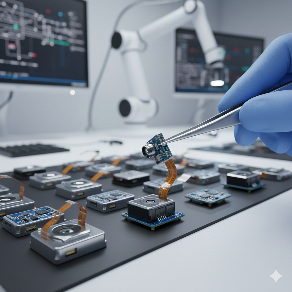
Miniature Camera Module Manufacturer: Compact Imaging Solutions for Smart Devices
As devices become thinner, lighter, and more mobile, the demand for smaller imaging systems continues to rise.
A miniature camera module manufacturer specializes in designing compact imaging hardware that fits into extremely tight spaces while still delivering clarity, stability, and consistent imaging performance.
These modules power wearables, smart home devices, handheld scanners, medical tools, IoT sensors, and robotics, where space constraints and low power consumption define the device structure.
1. Imaging Architecture Optimized for Size-Constrained Devices
Miniature camera modules are designed around strict dimensional limits, typically:
-
5.0 × 5.0 mm
-
4.0 × 4.0 mm
-
3.0 × 3.0 mm
-
Even sub-3 mm sizes for medical and industrial applications
To maintain imaging performance within these boundaries, manufacturers adjust:
-
CMOS sensor format (1/10" to 1/6")
-
Pixel size (1.1–1.75 μm) optimized for brightness
-
Low-power ISP tuning for wearable or battery-powered devices
-
Compact optical stack height while preserving clarity
This combination produces a module capable of capturing high-quality images despite a footprint small enough to fit on a fingertip.
2. Optical Design for Miniaturized Modules
Miniature modules rely on a compact optical stack that balances size with clarity. Their lenses—typically 3 to 5 small plastic or hybrid-glass elements—are shaped to control distortion and maintain sharpness at close-to-medium ranges. A wider aperture, often around F2.0–F2.4, compensates for the smaller sensor by bringing in more light.
Depending on the application, modules use either an IR-cut filter for natural color reproduction or NIR-pass coatings for medical and industrial imaging. Because every component sits in a tighter structure, lens alignment becomes extremely sensitive: even a slight deviation can shift the entire focal plane. Precise assembly is therefore essential to preserve uniform image quality across such a small footprint.
3. Micro PCBA and FPC Structures Supporting Compact Integration
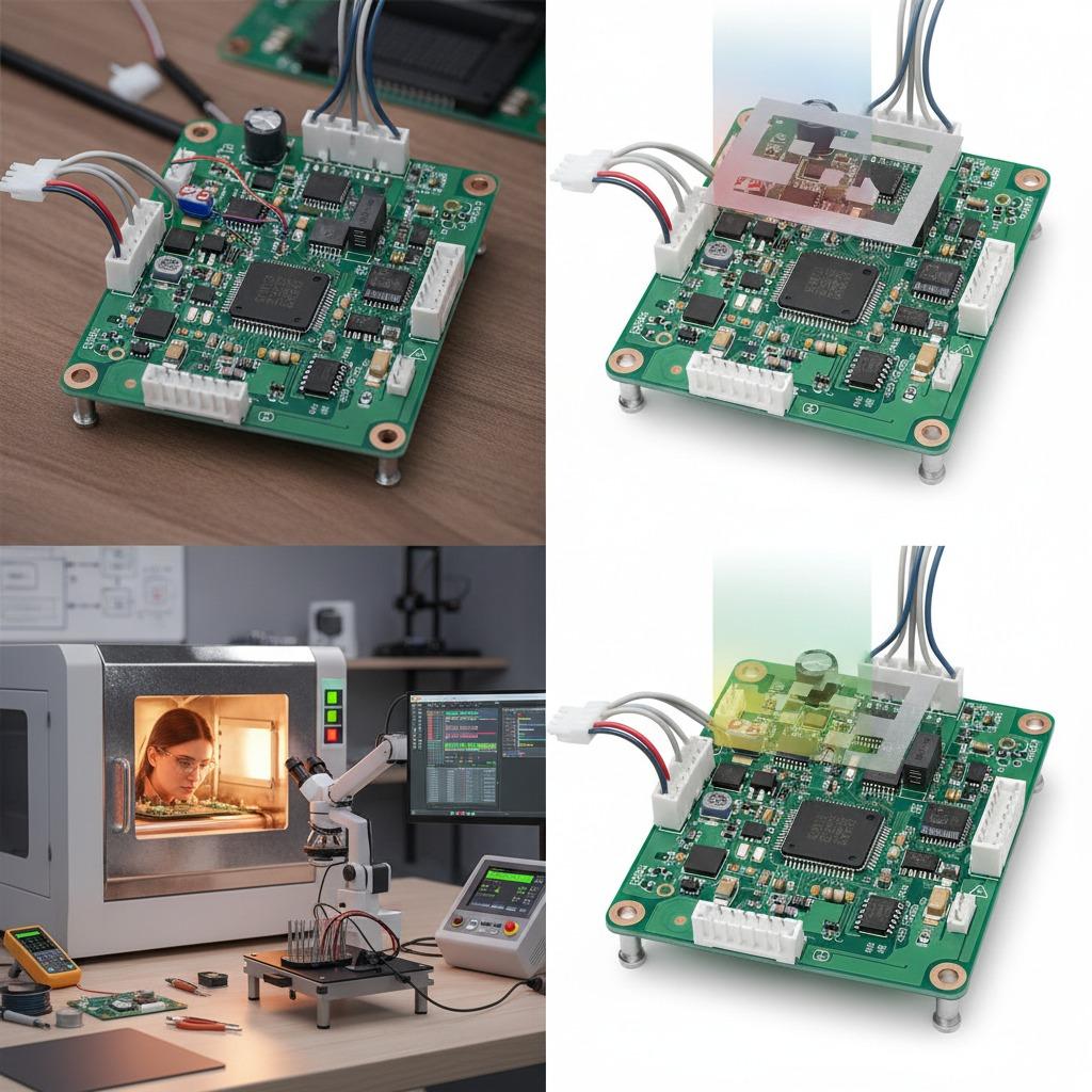
Miniature camera modules often rely on flexible printed circuits (FPCs) or ultrathin PCBAs to reduce size and improve mounting flexibility.
PCBA design considerations include:
-
High-density routing supporting MIPI or DVP output
-
Low-ripple power delivery for stable sensor operation
-
Compact EMI shielding layers
-
Thermal pathways designed for fanless devices
-
Integration with flexible FPC tails for spatial routing
These design techniques allow manufacturers to create modules suitable for tightly enclosed environments such as wearables, handheld scanners, and medical tools.
4. Sensor Bonding Techniques for Ultra-Compact Form Factors
Miniature modules require advanced bonding and assembly processes:
-
Chip-on-board (COB) for the smallest footprints
-
Chip-on-FPC where bending and flexibility are required
-
Automated die bonding for consistent alignment
-
Low-height lens holders with UV adhesive locking
-
Optical axis calibration ensuring clarity across compact lenses
These methods maintain structural stability even when the module is subjected to vibration, pressure, or continuous movement.
5. Core Performance Features of Miniature Camera Modules
Despite their size, miniature modules often support advanced imaging functions:
-
Low-light enhancement algorithms
-
High dynamic range (HDR/WDR)
-
Motion-adaptive processing for wearables
-
Low-power modes for battery-driven devices
-
High-frame-rate options for scanning and robotics
-
Compact autofocus or fixed-focus variants
Performance tuning ensures the module remains useful across diverse environments — indoor, outdoor, static, or fast-moving.
6. Testing Requirements for Miniature Modules
Because miniature modules are used in safety-critical or high-duty applications, reliability testing is extensive.
| Test Type | Purpose | Range/Standard |
|---|---|---|
| MTF & resolution test | Sharpness and image uniformity | Full-frame evaluation |
| Thermal cycling | Component stability in compact housings | -20°C to +70°C |
| Vibration testing | Durability for mobile or wearable devices | Multi-axis profiles |
| Aging test | Long-term runtime validation | 48–120 hours |
| Focus & alignment test | Optical accuracy | ±5 μm tolerance |
| Humidity resistance | Prevent fogging and condensation | 60°C / 90% RH |
These procedures guarantee the module remains stable even in tightly enclosed device structures.
7. Applications Enabled by Miniature Camera Modules
Miniature modules power a wide range of compact devices:
Wearable and Consumer Electronics
-
Smart glasses
-
Fitness bands
-
Body cameras
-
Mini drones
Medical and Industrial
-
Portable diagnostic tools
-
Inspection equipment
-
End-of-arm robotic sensors
-
Micro barcode scanners
IoT and Smart Home
-
Motion sensors with imaging
-
Ultra-compact indoor cameras
-
Smart access devices
Their size and flexibility open opportunities for new device categories where traditional cameras cannot fit.
8. Why Work With a Professional Miniature Camera Module Manufacturer
Manufacturers specializing in miniature modules provide several advantages:
-
High-density assembly capabilities (COB, COF, ultra-thin PCBA)
-
Advanced optical alignment systems suitable for sub-4 mm designs
-
Custom module design for shape, tail length, aperture, and interface
-
Stable supply for long-term IoT and wearable products
-
Support for mass production with strict consistency control
This gives device makers confidence when developing compact or innovative imaging products.
Compact Size, Full Capability: The Value of Miniature Camera Modules
A miniature camera module may be small, but its quality depends on the same principles that guide larger imaging systems: optical clarity, stable electronics, thermal balance, and consistent calibration.
A specialized manufacturer ensures these elements fit into a tiny form factor without sacrificing performance.
To explore miniature camera module solutions tailored to your device, visit www.hcdpcba.com or contact our team via the inquiry page for professional support.