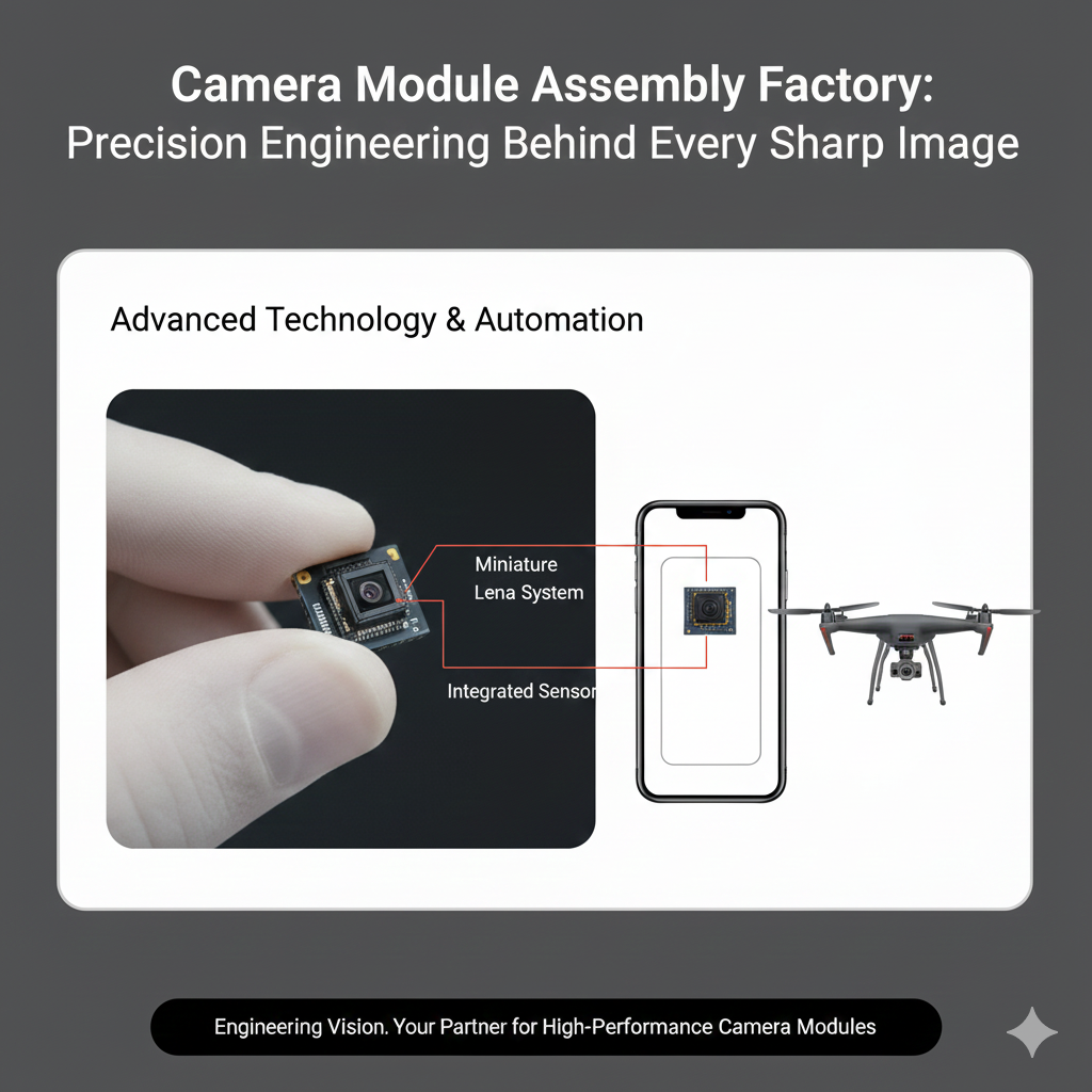
Camera Module Assembly Factory: Precision Engineering Behind Every Sharp Image
Every perfect photograph begins with precision you can’t see.
Inside every smartphone, automotive camera, or industrial vision sensor, the camera module assembly factory is where electronics meet optics, and where one micron of error can determine image quality.
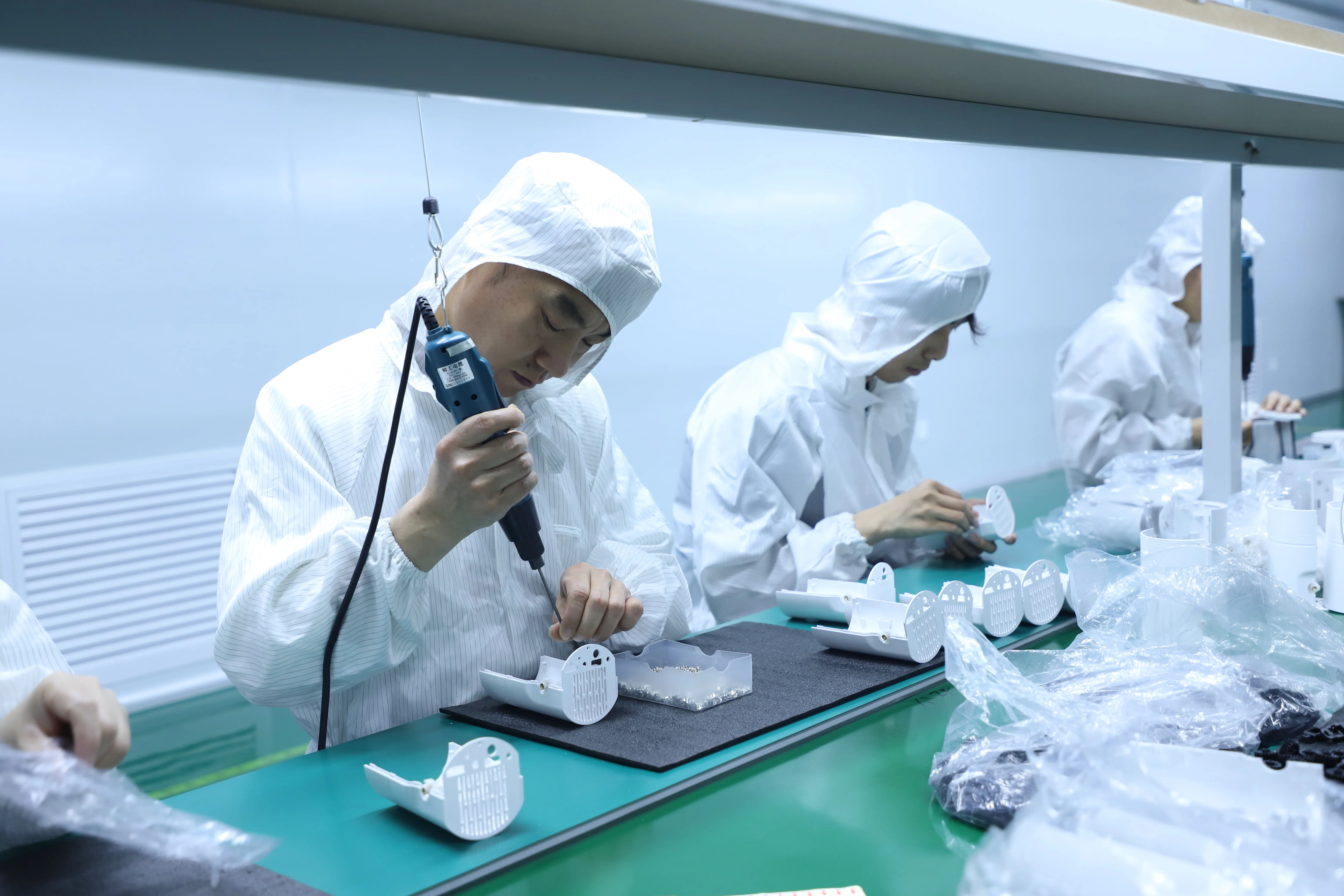
In these cleanrooms, engineers and machines collaborate to align CMOS sensors, attach lenses, and calibrate focus with microscopic precision—ensuring every frame captured is accurate, stable, and free from distortion.
Integration of Optics and Electronics
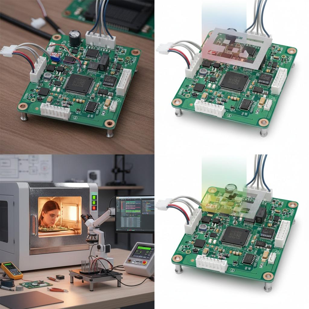
The modern camera module PCBA merges advanced circuit control with optical precision.
This combination enables high-speed data processing, real-time image correction, and intelligent focus tracking.
| Component | Function | Manufacturing Focus |
|---|---|---|
| CMOS Sensor | Converts light to electrical signals | Dust-free mounting, static protection |
| Lens System | Focuses light onto the sensor | Optical axis alignment ≤ 3µm |
| Driver PCBA | Controls exposure, gain, and focus | Impedance matching, thermal control |
| FPC/Connector | Links to the mainboard | Flex resistance and signal integrity |
| Housing Assembly | Holds all parts in position | Dimensional tolerance ±0.01mm |
The fusion of these elements transforms raw light into reliable, color-accurate data—a foundation for advanced imaging technologies like facial recognition, automotive ADAS, and machine vision inspection.
CMOS Sensor Alignment and Bonding
Sensor placement is the most critical step in module assembly.
Even a deviation of a few micrometers can cause focus blur or color shift.
Professional factories implement:
-
Vacuum pick-and-place systems to avoid static or dust contamination.
-
Active alignment techniques where sensors are optically calibrated in real-time.
-
UV-curing adhesives with sub-micron shrinkage control.
-
3D optical inspection to verify coplanarity and tilt angle.
-
Automated bonding under cleanroom Class 1000 or higher to prevent micro-particle interference.
This level of control ensures the sensor plane matches the lens axis precisely, resulting in uniform focus across the entire image.
Lens Assembly and Optical Calibration
Lens installation defines the visual clarity of the camera module.
Factories utilize multi-point lens calibration to fine-tune optical centers and correct for aberrations.
| Calibration Step | Objective | Technology Used |
|---|---|---|
| Optical Axis Alignment | Match lens and sensor center | Vision-guided alignment systems |
| Focus Adjustment | Ensure sharpness at varying distances | Laser-assisted autofocus calibration |
| Color Correction | Balance chromatic distortion | Spectrometer feedback control |
| Optical Seal Curing | Maintain mechanical stability | UV-controlled epoxy sealing |
| Final Inspection | Verify sharpness and exposure | AI-based focus detection software |
The process blends mechanical precision with optical science, ensuring each lens system maintains long-term consistency—even under vibration or temperature changes.
Cleanroom Assembly and Environmental Control
Optical assembly demands cleanroom manufacturing where dust, humidity, and electrostatic discharge are tightly regulated.
Professional camera module assembly factories maintain:
-
Class 100–1000 cleanrooms for optical bonding zones.
-
Ionized air systems to neutralize static during sensor placement.
-
Humidity control (40–55%) to stabilize adhesive performance.
-
HEPA filtration with 99.97% particle removal efficiency.
-
Temperature regulation (22±1°C) for consistent optical alignment.
Even a single dust particle can scatter light, introducing permanent artifacts in the captured image. That’s why environmental precision is as critical as mechanical alignment.
Auto-Focus and Image Stabilization Modules
The latest imaging modules integrate auto-focus (AF) and optical image stabilization (OIS) systems, requiring advanced miniaturization.
To achieve this, factories adopt:
-
Voice coil motor (VCM) integration for dynamic lens movement.
-
MEMS-based stabilization to counteract motion blur.
-
Embedded firmware calibration for response speed and focus accuracy.
-
High-frequency FPC design to handle control signals with minimal delay.
-
Closed-loop testing systems that verify focus range in milliseconds.
Such modules are vital for smartphones, drones, and automotive vision, where fast and stable focus performance defines end-user experience.
Quality Validation and Reliability Testing
Before shipment, every camera module undergoes comprehensive reliability testing.
| Test Type | Purpose | Conditions |
|---|---|---|
| Vibration & Drop Test | Validate mechanical stability | 3-axis, 30Hz–500Hz range |
| Thermal Shock Test | Assess temperature resilience | -40°C to +85°C |
| Aging Test | Simulate long-term operation | Continuous 72h function test |
| Image Quality Test | Check focus, color, and noise | Automated optical evaluation |
| Moisture Resistance Test | Prevent fogging and corrosion | 60°C, 90% RH for 48h |
These tests ensure every camera module performs with precision and durability across diverse use cases—from smartphones to automotive ADAS cameras.
Why Choose a Specialized Camera Module Assembly Factory
Working with an experienced camera module supplier in China offers multiple advantages:
-
Integrated Process Chain – From PCBA to lens assembly and firmware calibration.
-
Cleanroom Manufacturing – Environmentally controlled to optical-grade standards.
-
High-Precision Alignment Equipment – Ensuring sub-micron accuracy for every batch.
-
Customization Capabilities – Tailored modules for industrial, consumer, and automotive sectors.
-
Full Traceability – MES-driven process control for data-backed consistency.
This combination of technology, quality, and scalability helps global OEMs shorten R&D cycles and guarantee mass-production reliability.
From Precision Assembly to Perfect Vision
Every sharp image starts with microscopic precision.
A professional camera module assembly factory doesn’t just assemble parts—it builds trust in visual accuracy, one sensor and one lens at a time.
For OEMs seeking high-yield, dust-free, and precision-calibrated camera modules, explore our capabilities at www.hcdpcba.com or reach our technical team through the contact page.
Because every frame of clarity begins with flawless assembly.