
Overview
The Hybrid Inverter Control Board is the core control layer inside a solar-plus-battery power system when the buyer needs stable switching, coordinated charging, and safe energy routing between solar input, battery storage, and grid or backup power. In practice, this kind of board helps solve a common integration problem: the power stage may be capable of handling energy flow, but without a reliable control PCB, the inverter cannot manage timing, protection, sensing, or relay action with the consistency required for field use.
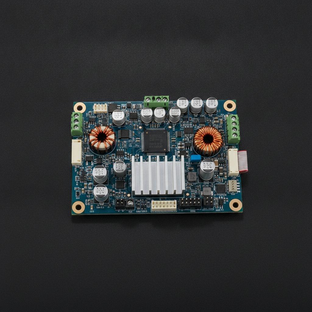
Based on the pictured assembly, this board is a rigid PCB/PCBA with a compact rectangular layout, mounting holes, dense surface-mount parts, multiple connectors, large electrolytic capacitors, inductive components, relay-style power blocks, and a central MCU. Visible artwork on the board indicates functions such as MPPT CONTROL, IGBT DRIVE, and BATTERY PROTECTION, which suggests a controller designed for hybrid inverter operation rather than a simple auxiliary interface card.
Product Reference
This Hybrid Inverter Control Board appears to be an integrated inverter control and power-interface assembly. The layout shows separate zones for logic, sensing, and power-related support components, which is typical in an Inverter PCBA Board that must manage control signals while staying physically compact. The board also includes multiple wire-to-board connectors, so it is likely intended to connect to sensors, relays, power stages, communication lines, and external harnesses inside a finished inverter enclosure.
Because the visible material does not confirm exact voltage ratings, current capacity, firmware functions, or communication protocols, it should be treated as a control-board platform rather than a fully specified end product. That makes it suitable for engineering review, OEM adaptation, or replacement-board sourcing where the buyer needs the physical architecture and functional class to match an existing design.
Key Capabilities
Control and coordination
The main role of a Solar Hybrid Inverter Control Board is to coordinate how power is accepted, converted, and redirected inside the inverter system. The visible MCU suggests a central controller handling timing, monitoring, and decision logic. In a hybrid power architecture, that typically means managing source priority, load behavior, charging decisions, and safety responses.
Power interface support
Visible inductors, capacitors, and relay-related components indicate that the board is not limited to low-power logic. It likely supports signal conditioning and control of higher-energy sections through driver circuits and switching interfaces. The presence of an aluminum heatsink on the board supports the idea that some components generate meaningful thermal load during operation.
Monitoring and protection logic
The artwork marking BATTERY PROTECTION points to an emphasis on system safety. In a Solar Inverter Control Board, that can include over-voltage, under-voltage, charge/discharge coordination, and relay control logic, although exact thresholds are not visible and should not be assumed.
Materials and Layout
The board uses a rigid PCB substrate with a solder mask finish and silkscreen reference markings. The assembly combines black, silver, beige, and metallic components, which is standard for mixed-signal power control hardware. Rounded corners and four mounting holes help with enclosure integration and mechanical stability. The layout keeps the controller near the center while distributing support parts around the edges, a practical arrangement for signal routing and heat management.
Visible connector variety is one of the clearer selling points. It indicates that the Hybrid Inverter Main Board is designed to interface with external wiring rather than operate as a sealed standalone module. For buyers, that often matters more than appearance: easy harness connection can simplify assembly, service, and replacement.
Manufacturing and Assembly
This type of board is typically built as a PCB assembly using SMT placement and reflow soldering for the majority of components. Through-hole or soldered connectors may be added for stronger mechanical retention. Power magnetics, relays, and larger capacitors are usually positioned after the smaller control parts to support both electrical performance and serviceability. Those are standard manufacturing practices for an inverter control platform, though the exact process used on this board is not confirmed by the image.
For buyers working with hcdpcba, the relevant service scope includes PCB prototyping, SMT placement, component sourcing, assembly, testing, OEM, and ODM support. That makes the company relevant not only for finished boards, but also for design transfer or replacement development when a Solar Hybrid Inverter Control Board must be adapted for a new housing or system architecture.
Typical Application Scenarios
This board class is commonly used in hybrid solar inverters, battery energy storage systems, grid-tied or off-grid backup units, and residential or light commercial renewable-energy equipment. It may also fit DC/AC control in systems that need to coordinate solar input, battery discharge, and utility power. In those environments, the control PCB is often the part that determines whether the inverter behaves predictably during load changes and source transitions.
For system builders, the important point is not only whether the board can switch power, but whether the control logic is robust enough to keep operation stable during real-world variations such as fluctuating solar input or battery state changes.
Quality Control and Buyer Considerations
Because electrical ratings and certifications are not visible here, buyers should confirm interface voltage, current demands, supported battery chemistry, connector pinout, firmware expectations, and protection strategy before ordering. If the board is intended as a replacement, the mechanical footprint and harness compatibility should be verified first. If it is for a new design, thermal margin, relay life, and PCB stack-up are worth reviewing early.
When sourcing an Inverter PCBA Board, ask for assembly test coverage, incoming material checks, and functional validation against the target inverter topology. For hybrid applications, the best fit usually comes from matching the control architecture to the system’s battery and source-management strategy rather than looking only at the board size or component count.
Customization and Next Steps
hcdpcba supports SMT, PCB assembly, component sourcing, testing, DFMA review, OEM, and ODM services, which makes it a practical partner for custom inverter control hardware. If you need a custom Hybrid Inverter Control Board, share your schematic, pinout, enclosure limits, thermal constraints, and target application so the assembly can be aligned with the final product requirements.
For project discussions, prototype builds, or manufacturing support, contact hcdpcba at +86 18924624188 to review the board structure and confirm how it can be adapted for your inverter platform.