
ESP32-32E Embedded Display and Control Board
The ESP32-32E is an embedded development and human-machine interface board designed for products that need local data presentation, wireless connectivity, and peripheral control in a compact assembly. It addresses a common buyer problem: combining a display, user input, storage, programming access, and communication interfaces without developing every circuit as a separate module. The supplied product information indicates an ESP32-based platform with an integrated display, USB Type-C, serial connections, removable storage, buttons, and expansion points.
Product Overview
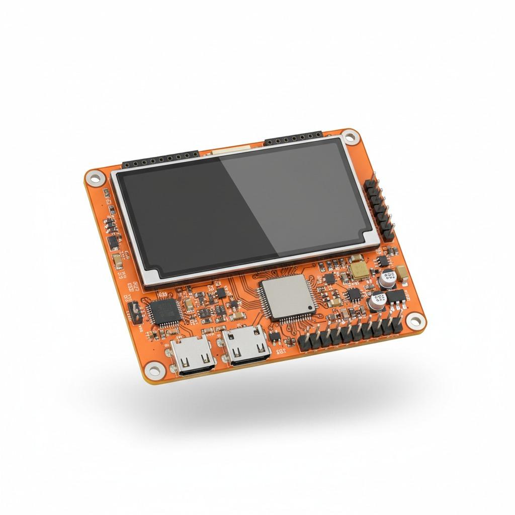
Visible versions of the board use a flat rectangular PCB with rounded corners and four mounting holes. The ESP32-32E module is installed on the board, while connectors and test or programming points are arranged around the display and control circuitry. Depending on the pictured version, the display is identified as a 2.8-inch LCD with 240 × 320 resolution and a resistive touch function, while another supplied image does not state the display resolution or touch specification. Buyers should therefore confirm the exact hardware revision before placing a production order.
The board marking references a 2.8 Inch TFT LCD and compatibility with ILI9341 and ST7789 display controllers. These references describe visible or supplied interface information; they do not by themselves confirm brightness, viewing angle, color depth, refresh rate, or outdoor readability. The ESP32 platform is visibly associated with Wi-Fi and Bluetooth functions, but the exact memory configuration, antenna design, firmware, and wireless performance require technical confirmation.
Key Specifications and Capabilities
- ESP32-32E embedded wireless controller module.
- Integrated display; one stated version is a 2.8-inch, 240 × 320 LCD.
- Resistive touch interface identified on the relevant board marking.
- USB Type-C connector for a function that should be confirmed as power, programming, data, or a combination.
- UART-labeled serial connectors and an SPI external interface.
- MicroSD or TF card interface for removable data storage.
- Expansion input-pin connector for connection to sensors, switches, or other circuits.
- Reset and boot buttons on the clearly identified version; another image shows two buttons whose individual functions are not specified.
- RGB indicator connection or onboard RGB lighting reference.
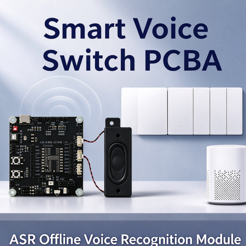
- Visible audio-related references, including a Speaker Interface and microphone functions on one supplied graphic.
- Four mounting holes for fixture or enclosure integration.
Materials, Finish, and Mechanical Integration
The board appears to use a rigid fiberglass-based PCB, possibly an epoxy laminate such as FR-4, although the exact laminate is not specified. Supplied images show orange or yellow solder-mask finishes, white or dark board markings, exposed metallic connector contacts, and surface-mounted electronic components. The ESP32 module includes a metal shielding cover in one visible version. PCB thickness, layer count, dimensions, mounting-hole spacing, display cover construction, and enclosure compatibility remain subject to drawing confirmation.
Manufacturing Process and Services
This product is consistent with an assembled printed circuit board requiring PCB fabrication, SMT placement, connector installation, display integration, and possible firmware loading. Some connectors or push-buttons may use through-hole mounting, but the exact assembly mix is not confirmed by the images. A typical production review would cover the bill of materials, PCB data, display and touch-panel sourcing, connector pinout, programming requirements, and functional test points.
hcdpcba provides PCB prototyping, SMT placement, PCBA assembly, component sourcing, assembly, testing, DFMA review, and OEM or ODM support. These services can be used to move from an evaluation board or reference design toward a repeatable production assembly. The company states that it supports small-batch and larger-batch SMT production and serves industrial control, security, medical, automotive electronics, IoT, communications, and smart-home applications.
Application Scenarios
The board can support IoT HMI Display Board concepts such as sensor gateways, equipment status panels, smart-home controllers, and compact configuration terminals. A local graphical display can present measurements, operating states, menus, or alarm information, while serial and SPI connections allow communication with external devices. The MicroSD interface is relevant to portable data loggers, test instruments, and monitoring equipment that must retain records locally.
Wireless prototypes may use the ESP32 platform for network-connected instruments, telemetry units, robotics controls, and educational development systems. A Bluetooth BLE connection may be useful for nearby setup or service functions when supported by the selected firmware and hardware configuration. Audio-enabled terminals can also be evaluated where a Speaker Interface or microphone connection is required, but codec, amplifier, output power, and audio file support must be verified separately.
Quality Control and Verification
Before production approval, buyers should request inspection of PCB workmanship, component orientation, solder joints, connector fit, display operation, touch response where applicable, button function, USB behavior, card detection, serial communication, and wireless operation. A suitable test plan should be based on the final schematic and firmware rather than on board labels alone. hcdpcba identifies component sourcing, assembly, and testing as available services; the specific inspection equipment, test coverage, acceptance criteria, and reports should be agreed in the quotation or engineering review.
Customization Guidance
For a custom version, provide the required display size and resolution, controller compatibility, touch technology, enclosure envelope, mounting-hole pattern, power source, battery requirements, connector orientation, and firmware interface. Also specify whether USB Type-C is used for charging, programming, data transfer, or power only. UART voltage levels, SPI assignments, storage requirements, antenna clearance, audio functions, and operating temperature should be documented before layout release.
DFMA review is useful when the board will move from prototype quantities to regular production. It can identify access problems around connectors, display installation risks, component availability issues, test-point requirements, and assembly constraints. Exact operating limits, certifications, production capacity, lead time, pricing, and environmental ratings should be confirmed directly rather than inferred from the product images.
Buyer Decision Factors
Buyers should first determine which hardware revision matches the intended application. Confirm the display and touch specifications, ESP32 memory and wireless details, complete pinout, power requirements, card capacity, audio circuitry, and firmware support. Mechanical drawings are important because four mounting holes are visible, but their spacing and board dimensions are not supplied. For production use, evaluate component lifecycle, programming method, functional test coverage, sourcing responsibility, and the supplier’s ability to maintain the approved bill of materials.
Request a Technical Review
Contact hcdpcba at +86 18924624188 to discuss the ESP32-32E board, PCB assembly, component sourcing, testing, or a customized OEM and ODM requirement. Include the target application, expected quantity, display revision, required interfaces, enclosure constraints, and available design files. The engineering team can then clarify the verified specification and recommend a practical path from prototype evaluation to assembled production hardware.