
Professional Automotive PCBA Overview
Professional Automotive PCBA is used to turn a vehicle electronics concept into a stable, buildable circuit assembly. For automotive buyers, the main problem is not just making a board that powers on; it is keeping signal integrity, connector reliability, and assembly consistency under control when the design must fit into tight spaces and connect to many subsystems. In automotive electronics, a well-executed PCBA helps reduce rework, supports repeatable production, and creates a practical base for control, sensing, communication, and power management modules.
hcdpcba provides PCB fabrication and SMT assembly services for projects that need custom electronics built for industrial and automotive-related use cases. Based on the visible board category in the supplied material, the product reference here is a compact PCB assembly with a central IC, edge connectors, pin headers, and mounting points. That structure is common in embedded control hardware, gateway boards, and vehicle-related electronic modules.
Product Reference and Functional Role
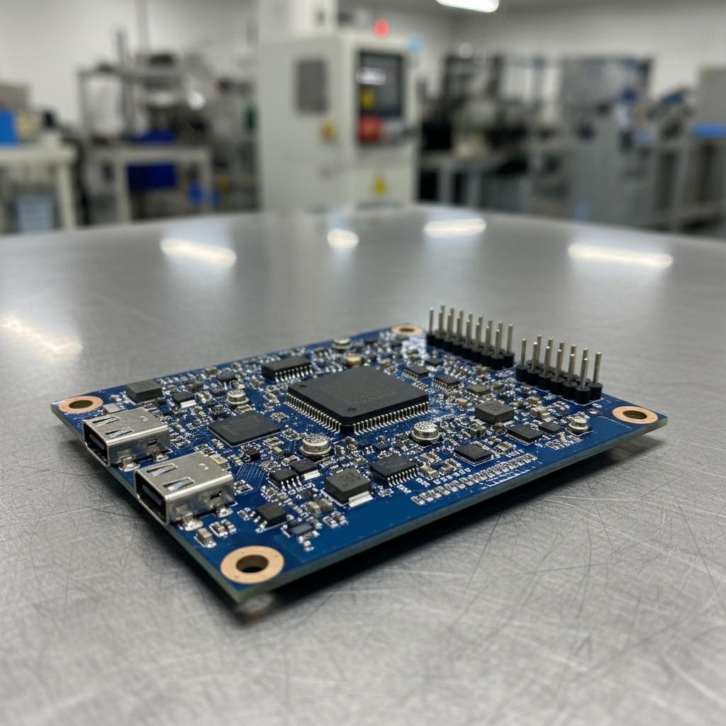
The visible assembly shows a rectangular blue PCB with a low-profile layout, multiple surface-mount components, and several external connection points. This type of board is typically used where control logic, peripheral interfaces, and data handling must coexist in a limited footprint. In automotive programs, similar boards may be applied in infotainment submodules, sensor interface units, control nodes, or test fixtures. The exact chipset, electrical ratings, and board specification are not identifiable from the image, so any final design decision should be based on the approved engineering files.
For buyers comparing a PCB & PCBA Manufacturing Service, the important point is whether the supplier can keep the assembly process aligned with the intended application. A compact automotive board often depends on accurate placement of fine-pitch parts, dependable solder joints, and clean connector alignment. These factors matter more than appearance alone.
Visible Specifications and Build Characteristics
Board Structure
The image shows a blue solder mask on a fiberglass-style substrate, likely FR-4 by appearance, though the exact laminate is not confirmed. The layout includes rounded corners, corner mounting holes, and exposed ring areas around the holes. Those details suggest the board is meant for secure mechanical fastening inside an enclosure or chassis.
Components and Interfaces
Several surface-mounted ICs and discrete parts are arranged around a larger central square package. Edge-mounted USB-type ports are visible, along with a row of pin headers and additional small connectors. This combination points to a board designed for both power/communication access and expansion or debugging. The visible part count also indicates a normal SMT assembly process rather than a simple bare PCB.
In automotive electronics, a layout like this can support communication with sensors, actuators, storage devices, or external modules. It can also serve in prototype builds where engineers need to verify signal routing before moving to a production package.
Materials and Finish Options
For this kind of assembly, the common material base is a fiberglass-reinforced PCB with solder mask protection and exposed copper features at pads, vias, and mounting points. Finish options for automotive-style projects may vary depending on the design, but the exact finish must be selected according to the BOM and process documentation. The supplied image does not confirm a specific surface finish, so it should be treated as a visual reference only.
When sourcing Professional Automotive PCBA for LED Car Light Driver modules, buyers often focus on heat handling, connector style, and board protection strategy. LED driver assemblies may require different component selection and thermal planning than logic boards, so the final specification should always match the lamp architecture and current profile.
Manufacturing and Assembly Process
hcdpcba lists SMT贴片, PCB打样, 元器件代采, 组装, 测试, and DFMA support. In practical terms, that means the production route can cover board fabrication, component sourcing, placement, soldering, and post-assembly verification. For automotive buyers, this end-to-end flow is useful because it reduces handoff errors between design, procurement, and manufacturing.
A typical PCBA workflow includes file review, manufacturability checking, stencil and paste preparation, component placement, reflow soldering, inspection, and electrical test. When the product is intended for vehicles or vehicle-adjacent systems, process control becomes especially important because connector reliability and assembly repeatability affect downstream integration.
Application Scenarios
This type of assembly fits a broad range of embedded and automotive-related applications. Common use cases include control modules, gateway devices, machine vision support boards, sensor hubs, robotics controllers, IoT edge devices, and development platforms. Within automotive electronics, boards with similar layouts may be used in prototype ECUs, display subsystems, lighting control, or communication interface units.
The board form factor shown is also suitable for product development teams that need a compact prototype before committing to a custom housing or a finalized production layout. For system integrators, the mounting holes and edge connectors make it easier to position the board in a larger assembly.
Quality Control and Buyer Considerations
Quality control should cover solder joint consistency, placement accuracy, connector orientation, and assembly cleanliness. hcdpcba states that it offers testing and quality assurance support, which is useful for buyers who need reliable assembly rather than only bare fabrication. In automotive projects, the buyer should also confirm documentation needs, acceptance criteria, and any special inspection requirements tied to the end application.
When evaluating a supplier, consider whether the factory can support small-batch prototyping as well as larger runs, whether component sourcing is traceable, and whether DFMA feedback is available early enough to reduce redesign costs. These factors often matter more than a simple low-price quote.
Customization Guidance
Customization should start with the real operating environment. If the board will be used in a vehicle-related module, the designer should define connector type, mounting method, thermal path, power entry, and communication interfaces before production. For a Professional Automotive PCBA project, the BOM, Gerber files, assembly drawings, and test requirements should be aligned so that the final board can move cleanly from prototype to repeatable manufacture.
Because the visible image does not reveal exact electrical ratings or certifications, those details must be provided in the design package. That is the safest way to avoid assumptions that could affect validation later.
Start Your Project with hcdpcba
If you are building an automotive electronics module, embedded control board, or prototype assembly, hcdpcba can support PCB fabrication, SMT assembly, sourcing, and testing under one service flow. Share your design files and project requirements to receive a manufacturing plan that fits your application. For OEM and ODM needs, the team can help move from concept to assembled boards with a process focused on consistency and manufacturability.
Contact hcdpcba at +86 18924624188 to discuss your next PCBA project and review the best production route for your design.