
Industrial CCU PCBA for Ethernet and Control Equipment
Industrial CCU PCBA is a suitable starting point for OEMs developing industrial networking, embedded control, or communication equipment that needs several wired interfaces on one custom board. The visible assembly appears to address a common buyer problem: integrating multiple communication ports, field-wiring terminals, protection functions, and control circuitry into a board designed for a larger machine or enclosure. Because the available information comes from board images and service data, the exact electrical function must be confirmed against schematics, a bill of materials, and test requirements.
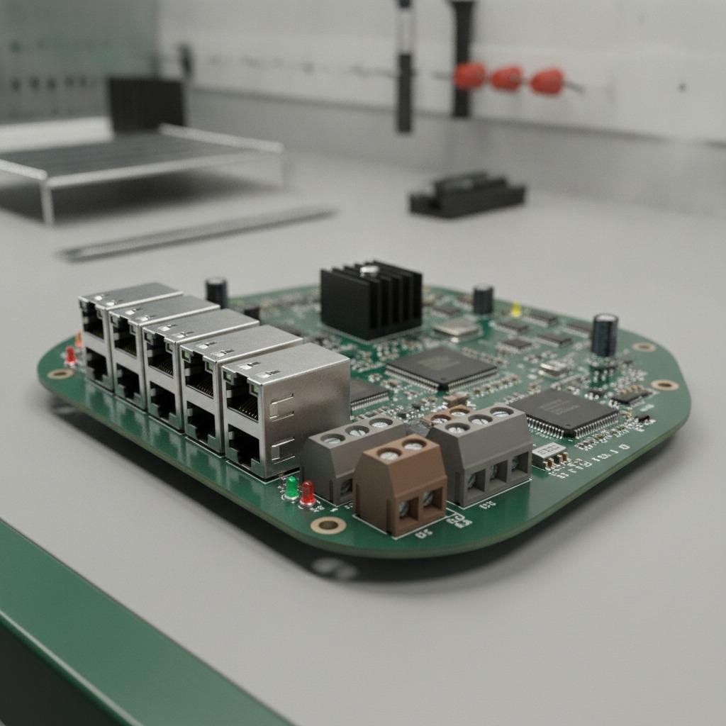
Product Overview
This product is a custom populated printed circuit board for industrial Ethernet, automation, or electronic test applications. The green rigid board has a non-rectangular, stepped outline with rounded corners, mounting holes, copper routing, solder mask, and white reference markings. Several shielded RJ45-style modular connectors are visible along one edge. Depending on the final circuit design, these ports could support an Ethernet switch, gateway, embedded controller, communication I/O module, or evaluation platform. The image alone does not establish the port speed, switching architecture, protocol support, or final product name.
The assembly also includes pluggable screw-terminal blocks, an additional shielded connector that may be USB-style or another communications interface, red and black header or selector components, integrated circuits, passive components, LEDs, and protection-related parts. A central yellow rectangular component is visible, but its electrical function cannot be identified reliably without the schematic or component designator.
Key Specifications and Capabilities
- Custom rigid PCB assembly with mixed surface-mount and through-hole components.
- Multiple shielded RJ45-style ports for a high-density wired communication interface.
- Pluggable terminal blocks for accessible power, alarm, sensor, auxiliary I/O, or signal wiring, subject to the approved circuit design.
- Board-mounted configuration or selection hardware, including a visible DIP-style component or header.
- Perimeter and offset mounting holes for integration into a control panel, enclosure, machine assembly, or test fixture.
- Support for PCB fabrication, component sourcing, SMT placement, through-hole assembly, inspection, and testing through hcdpcba.
Important electrical values remain project-specific. Ethernet speed, MAC and PHY configuration, switching capacity, isolation arrangement, PoE capability, input voltage, current consumption, operating temperature, dimensions, layer count, copper weight, and connector pin assignments should not be assumed from the image.
Materials and Finish Options
The visible board appears to use a fiberglass-reinforced epoxy construction, commonly associated with FR-4, with green solder mask and white silkscreen. However, the laminate grade is not confirmed. During quotation, buyers can specify the required PCB material, layer count, finished thickness, copper weight, impedance requirements, surface finish, solder mask color, silkscreen markings, and edge or slot features. The appropriate surface finish may depend on connector type, storage conditions, assembly volume, and reliability requirements; it should be selected from the approved fabrication drawing rather than inferred from the photograph.
Metal-shielded connectors are visible, but their plating, shielding design, contact material, and mechanical retention are not documented. Terminal block pitch, current rating, wire-entry direction, and locking method should also be defined before production.
Manufacturing Process
A typical production route begins with design-for-manufacturing and design-for-assembly review. hcdpcba provides DFMA support to identify component spacing, polarity marking, solder-joint access, connector keep-out areas, mounting-hole requirements, and possible assembly risks. After the design package is approved, the process may include PCB fabrication, component procurement, solder paste printing, automated SMT placement, reflow soldering, through-hole insertion, and selective, wave, or manual soldering for larger connectors and terminal blocks.
For an evaluation board or prototype, engineering builds can help confirm port arrangement, terminal wiring, mechanical fit, and test access before a larger run. The exact production method depends on the component mix, board geometry, approved quantities, and quality requirements.
Application Scenarios
Industrial Networking and Automation
The board may be integrated into industrial Ethernet equipment, machine-control electronics, automation gateways, data-acquisition hardware, or custom communication modules. Multiple RJ45-style ports can simplify wiring in systems that require several network connections, although the supported network function must be verified by electrical and firmware documentation.
Control Panels and Embedded OEM Products
Terminal blocks and distributed mounting holes make this type of assembly relevant to control-panel products and equipment with field wiring. The irregular outline may be intended to fit around other mechanical features inside an enclosure. No enclosure, DIN-rail standard, ingress rating, or final mounting compatibility is confirmed, so mechanical drawings should be exchanged during project review.
Engineering and Evaluation Work
The visible configuration hardware and accessible connectors are also consistent with a test or evaluation platform. Such a board can support laboratory investigation of signal isolation, power protection, port expansion, communication interfaces, or embedded control functions. Bench testing does not, by itself, prove suitability for continuous field operation.
Quality Control and Testing
Quality planning should cover incoming component verification, PCB inspection, placement accuracy, solder-joint inspection, polarity checks, connector retention, and final electrical testing. Depending on the design, buyers may request automated optical inspection, X-ray inspection for hidden solder joints, continuity testing, programming, functional test, isolation verification, or power-up testing. The required test limits must be supplied by the customer because no isolation voltage, surge rating, ESD rating, thermal limit, or performance test result is provided here.
hcdpcba reports services covering component sourcing, assembly, and testing, as well as prototype and production support. A project quality plan can define inspection records, traceability expectations, approved substitutions, nonconformance handling, and release criteria. Certification status and compliance results should be confirmed for the specific finished assembly rather than presumed from the board appearance.
Customization Guidance
For an accurate quotation, provide Gerber or ODB++ fabrication data, assembly drawings, schematics, pick-and-place files, bill of materials, approved manufacturer lists, and test documentation where available. Also specify the required port count, connector orientation, terminal-block layout, mounting-hole pattern, board dimensions, environmental conditions, and whether firmware loading is part of the service.
Buyers should clearly identify whether the assembly is a Central Control Unit Board, a communications interface, a test platform, or another custom design. If the intended product is an Industrial Communication PCBA or Multi RJ45 Ethernet Control Board, protocol, speed, isolation, power, and thermal requirements should be stated explicitly. This prevents a visual resemblance from being mistaken for a confirmed electrical specification.
Buyer Decision Factors
- Confirm the required network architecture, port count, speed, protocol, and isolation method.
- Check mechanical fit, mounting-hole tolerances, connector access, and cable bend space.
- Define component sourcing rules, lifecycle expectations, substitutions, and obsolescence controls.
- Match inspection and functional testing to the actual product risk.
- Decide whether the project needs prototype support, small-batch assembly, or volume manufacturing.
- Review confidentiality, OEM or ODM responsibilities, documentation ownership, and change-control procedures.
Request a Custom PCBA Review
hcdpcba supports PCB prototyping, SMT placement, component procurement, assembly, testing, OEM, ODM, and DFMA services for industrial control, communications, medical, automotive, power, IoT, and related electronics. Send the board files, component list, intended application, estimated quantity, and required tests for a technical review. The team can then confirm the feasible manufacturing process, identify missing specifications, and prepare a project-specific quotation for this Industrial Control PCB Assembly.
For direct contact, hcdpcba lists the telephone number +86 18924624188.